![]() If you've ever discussed photovoltaic solar panels with a proud owner, they will certainly have proudly shown you on their cell phone how much electricity they produce every day. With thermal solar panels, on the other hand, remote control is less widespread, as control systems are generally more primitive. So let's take a look at how you can add a simple monitoring system to your domestic water heating system, which could maybe save you a few hundred kWh a year...
If you've ever discussed photovoltaic solar panels with a proud owner, they will certainly have proudly shown you on their cell phone how much electricity they produce every day. With thermal solar panels, on the other hand, remote control is less widespread, as control systems are generally more primitive. So let's take a look at how you can add a simple monitoring system to your domestic water heating system, which could maybe save you a few hundred kWh a year...
The principle used in solar domestic water heating systems is to combine the solar source, which has the best ecological record but whose availability is not guaranteed, with a reliable but slightly less virtuous backup source, such as a heat pump or a district heating network.
The principle of the stratified hot water tank is generally used for this purpose: the heat exchanger with the priority source (solar) is placed at the base of the tank and can therefore heat the entire volume of water, while the additional exchanger located halfway up guarantees a minimum volume of water that will be heated even in the absence of sunshine. Because cold water is heavier than hot water, it always stays at the bottom of the tank, maximizing the potential of the solar heat exchanger. The additional heat exchanger only comes into operation when the water temperature at half-height is insufficient to meet requirements.
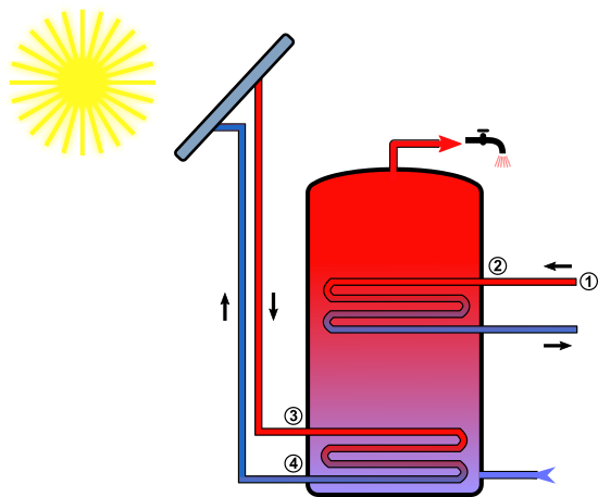
A domestic water heat tank with double exchangers
Measuring technology
To accurately count the proportion of heat supplied by the solar system in relation to the backup heat source, it would be necessary to install energy meters on both heat exchange circuits. This would be the most accurate solution, but it would mean modifying the piping to accommodate heat meters, which would be quite costly.
We're going to use a much simpler solution, which nevertheless offers a good view of how the system works. The idea is to attach small thermistors to the pipes at a few strategic points. Glued on with a simple metallized adhesive, these small temperature sensors provide a local measure of the pipe temperature, enabling heat exchanges to be traced.
A Yocto-MaxiThermistor can measure six different points, thanks to the six 10k NTC thermistors supplied with the module. These are simply extended with simple electrical wire and glued to the various measuring points.
For our experiment, we only needed four measuring points, whose indexes are shown on the schema above:
- at the start of the supplementary thermal network (district heating network)
- at the inlet to the supplementary heat exchanger tank (upper half of the tank)
- at the solar heat exchanger tank inlet
- at the solar exchanger tank outlet (tank base)
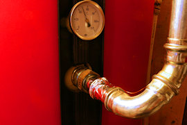
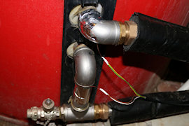
Attach thermistors to pipes using metallized adhesive tape
The first two points tell us without a doubt when the additional energy source is being used: when this exchanger is off, the pipe temperature is lower towards the heat source than towards the storage tank, whereas when circulation is active to heat the water, the source is warmer.
Similarly, the other two measuring points on the solar circuit enable us to observe circulation in the solar heat exchanger. With one point at the storage tank inlet and one at the outlet, we can observe the heat transfer that has taken place in the storage tank.
And since we have measuring points at the base and in the middle of the tank, we can check the effect of thermal stratification.
The thermistors are wired directly to the input of the Yocto-MaxiThermistor, which we connected to an existing YoctoHub-Ethernet used for another control system, but which could also have been connected directly via USB to a computer.
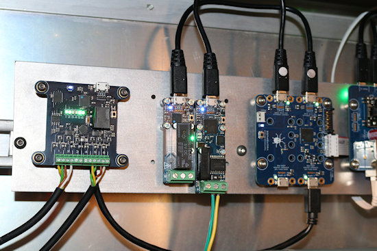
The Yocto-MaxiThermistor (left) collects the temperature measures
Data is sent via MQTT to Home Assistant, as described in this previous post.
Observations
After a few days' operation, Home Assistant has produced a graph showing how the two heat exchange circuits in the hot water tank work together:
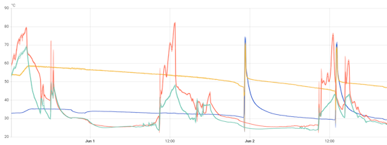
Temperature variations on the pipes provide a clear transcript of the events
- In blue, the flow temperature of the backup thermal network
- Yellow: the backup input to the tank (top half)
- Red: input from solar heat exchanger at the bottom of tank
- Green: storage tank outlet from solar heat exchanger
You can immediately see the solar input in red, which heats the storage tank every day at mid-day, and the solar return in green, a few degrees lower down after depositing heat in the storage tank. On May 31st, on the far left, we can see that solar heat raises the temperature at the upper measuring point.
On the second day, we can see that the solar contribution has not been sufficient to raise the temperature to the upper measuring point: the yellow curve continues to fall. In fact, as we can deduce from the green curve, which is much lower than the previous day, the temperature at the bottom of the storage tank was much lower, which did not allow the temperature to rise to the top. As a result, when hot water is used for showers at the end of the day, the backup thermal network (in blue) is activated, raising the temperature in the upper half of the tank. The same scenario occurs the next day at 1 p.m., when the dishes are washed after lunch: the residual heat in the tank is insufficient, and the additional heat exchanger is once again activated.
Deductions
In view of this graph, the first obvious conclusion is that solar energy inputs do not avoid the use of the backup energy source, contrary to expectations. The aim of this experiment was precisely to be able to trace the use of non-solar energy, and our measuring system therefore fulfills its role entirely.
Now we need to find out why solar energy is not enough... The solar energy delivered is considerable: we would expect it to compensate for the heat lost through the storage tank insulation, and even a little more; otherwise there would be no point in using a double-stage solar storage tank. However, measures taken on June 1 at midday show that the temperature in the upper half of the storage tank continues to drop despite the solar contribution. So there must be some heat loss elsewhere.
A detailed inspection of the tank reveals the most likely cause: hidden away at the back of the tank, a safety valve allows a continuous trickle of water to pass through unobtrusively. Probably blocked by limescale, the valve no longer closes properly and is probably responsible for the loss of liters of hot water over months, replaced by cold water, without anyone noticing :-(
All that's left now is to have it replaced... and then we should be able to check on the graphs that district heating is no longer used at all on sunny days!


