![]() You should normally power Yoctopuce modules with a voltage between 4.75V and 5.25V, which is the standard operating range for USB devices. But what happens when you go beyond these limits, even temporarily and without meaning to? What are the cases that can cause lasting damage? This is what we will explain to you...
You should normally power Yoctopuce modules with a voltage between 4.75V and 5.25V, which is the standard operating range for USB devices. But what happens when you go beyond these limits, even temporarily and without meaning to? What are the cases that can cause lasting damage? This is what we will explain to you...
We had several opportunities to study this issue: to answer customers who knew in advance that they were likely to step out of the intended power supply range, but also in a few cases some modules were returned to us because they had an abnormal behavior.
There are several scenarios which can lead to a temporary abnormal power supply, and it is even quite difficult to totally exclude all these conditions. Typical cases include:
- Systems powered from a battery: the voltage ends up dropping in the absence of an adequate recharge
- Power wires too thin and/or too long provoking a voltage drop (see our post on the topic). GSM hubs are particularly sensitive to this issue.
- Slow voltage decay when turning off the power supply, due to the discharge of large capacitors (brownout).
- Surge on the power supply at turn-on or caused by other components sharing the same power supply.
Some modules are more sensitive than others to a minor drift in the power supply range. But beyond a given threshold, the effects affect all the modules. We are therefore going to detail the issues which may occur:
Power supply dependent electrical functions
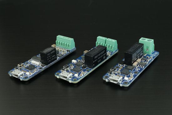
The most sensitive modules are those which have an isolated power supply whose output is strongly linked to the input voltage. All the electric sensors, electric interfaces, and actuators which use a 5V isolator are concerned. You can recognize the 5V isolator to its characteristic shape: a black monolith 10mm high, 6mm wide, and 10 or 20mm long.

The three types of 5V isolators used by Yoctopuce
For these modules, stick strictly to the prescribed power supply range of 4.75 V - 5.25 V if you want to guarantee normal operations.
Some modules provide a stabilized power supply above 4.5V used in the measuring process, derived from the input voltage. It's the Yocto-Bridge, Yocto-MaxiBridge, and the Yocto-MaxiMicroVolt-Rx. For these modules, it is even advisable not to go lower than 4.8V to ensure the stability of the measure.
For the Micro-USB-Hub and the YoctoHubs, respect the limited range as well to avoid surprises, as the power supply of the down ports depends on it. A single exception, the YoctoHub-Wireless-n can work down to 4V if you don't connect to it one of the sensitive modules that we just mentioned.
For all the other modules, the sensitive electronics is protected by an LDO regulator which guarantees correct operation on a wider range: 3.8 V - 5.5 V. Do not ever exceed 5.5V, as you may damage the microcontroller (MCU). And beware if you lower the voltage down to 3.8V: the module works normally autonomously, but you might have some surprises with the USB connection...
Minimum voltage for USB operation
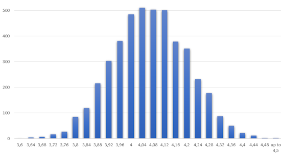
When the power supply voltage goes below 4.5V, you risk to lose USB communication between the host and the module. Indeed, the module considers that the voltage drop corresponds to a disconnection and stops communicating. Microchip, which manufactures the MCU that we use, doesn't precisely specify the exact voltage at which this disconnection occurs. We measured it on 5'000 modules coming from different Microchip deliveries and we obtained the following statistic:

Observed distribution of minimum USB voltage before disconnection
So, on average the disconnection occurs around 4V, but this can vary from 3.6V to 4.5V. We never observed a disconnection above 4.5V.
In case of a temporary voltage drop, due for example to a consumption peak, the module reconnects to USB as soon as the voltage goes back above the threshold.
There is no hysteresis between disconnection and reconnection, one or two hundredths of volt are enough to change the state in one way or the other. This can have a pernicious effect when the power voltage is exactly on the limit: the module risks to disconnect even before having achieved the packet exchange which follows the reconnection. Windows doesn't like this at all and sometimes decides to definitively ban the device which it considers to be so rude. The later then appears in the module manager with a question mark, and a restart of the machine or even sometimes a uninstallation of the module in the device manager is necessary to make it work again. The Microsoft pnputil tool as well as the devcon example in the Microsoft DDK will help you to automate this type of recovery process, if the situation is unavoidable. It is naturally better to completely avoid keeping a power voltage below 4.5V when a module is connected to a host by USB. Operation between 3.8V and 4.5V, on modules that allow it, is therefore to be used only on modules disconnected from USB, for example for the autonomous data logging of measures.
Dangerously low voltages: the brownout
Below 3.8V, the proper functioning of the modules is no longer guaranteed, but nothing truly damageable should occur as long as the voltage remains above 3V. Below 3V, a new danger appears: the brownout. It happens when an electronic circuit does not have enough voltage to properly switch bits from 0 to 1 and vice versa, and therefore wander in a strange world where logic rules are not respected, and where numbers changes spontaneously over time. An electronic circuit suffering from brownout is like a driver losing consciousness at the wheel: if the vehicle is stopped, everything is fine, but if it is running on a mountain road, it may cause some serious damage...
Digital electronic components are all exposed to this risk. To prevent it, some MCUs - among which the one we use - include a hardware protection which detects a power drop and immediately stops the code execution, before it does anything weird. But we had the opportunity to check that this protection is not necessarily enough. Recently, we reproduced a condition in which the brownout protection still led to a firmware corruption because its voltage threshold was lower than that required for the correct functioning of the MCU flash memory and of the external flash memory. We therefore had to add in October 2020 a software protection to our firmware, which checks that the power voltage is high enough before any access to the flash memory. If you use a firmware dating from earlier than October 2020 and if your module stops working due to a brownout, you can use the recovery process described in in the VirtualHub User's Guide under Alternative method 1 to give it a firmware and restore it.
Another brownout case that we just discovered concerns the external flash memory, for which we saw a case of spontaneous switching into read-only mode, on a system powered by a battery. This issue manifests itself with the apparition of the Fwerr message in the logs of the Yoctopuce module and by the impossibility to add data to the data logger or to configure a sensor calibration. We publish this week a new version of the firmware which automatically disables the read-only mode in case it was activated following a brownout and which therefore solves this issue.
To secure systems powered on a battery against brownout, we recommend as an additional measure to use the Mini-Battery-Supervisor. This products includes a voltage supervisor which measures the supply voltage and performs a clean shut down of the power supply as soon as the voltage goes below 3.5V, well before risks of brownout. The power supply is reestablished only when the voltage goes back above 4V, which prevents oscillations. You can also configure the Mini-Battery-Supervisor for higher threshold voltages, in order to protect not only the module but also the battery itself.
Specific case: the YoctoHub-GSM
Modules offering cellular connectivity are particularly exposed to temporary voltage drops because of the high consumption peaks during the transmission of GSM data. The danger comes in particular from the fact that these consumption peaks depend on the available technology (2G, 3G, 4G) and on the distance from the cell antenna to which the module is connected. The consumption during a 2G transmission typically produces peaks close to 2 amperes. In 3G, it keeps below 1 ampere, and in 4G it is lower than 0.5 ampere.
If you are not careful, you can end up with a prototype which works perfectly well in your working environment where 4G reception is good, but which suffers from brownout when it is installed in production in an area where 4G is not available. Brownout symptoms due to a consumption peak of the GSM module are the following:
- failure of the GSM connection although the module finds the network, with characteristic messages in the module logs
- USB disconnection when the GSM connection happens
- in the worst case, unrecoverable corruption of the flash memory of the GSM module itself
To avoid these issues, we recommend the following precautions:
- Use a properly sized power supply to power the GSM hubs
- Use a power supply wire as short as possible (for example 50cm)
- If you intend to allow usage of the 2G network in production, force the module in 2G mode during your tests and put yourself in bad GSM reception conditions to make sure to test the worst case scenario
- If you don't need to use the 2G network, explicitly disable it in the module configuration to prevent it from switching on during a temporary loss of 4G network for example
- Prevent as much as possible unexpected power outages or brownout conditions on the YoctoHub-GSM to avoid the corruption of the flash memory of the GSM module
- Install the new firmware that we publish this week and which lowers the brownout risk on the flash memory of the GSM module itself.
Conclusion
Contrary to what one might naively imagine, supplying an electronic module with insufficient voltage, even temporarily, can have damaging long-term consequences for the electronics. Take the time to check the behavior of your power supplies. If you can, the best way is to take an oscilloscope and to directly check on the module 5V pad that the power supply is truly at the expected value and stable, and that when turning the system off, the shut down is performed quickly and cleanly.


