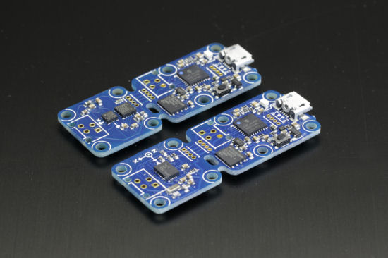
 The Yocto-3D is in the top 10 of the products we sell the most. Nevertheless, we have a problem with it: it doesn't allow us to calibrate a compensation for magnetic perturbations, and its firmware is choke-full, which prevents us from improving it. So we attacked the problem from a different angle and, today, we propose a new, similar product, but based on a more efficient sensor including hard iron magnetic compensation. Welcome to the Yocto-3D-V2...
Similarities
The Yocto-3D-V2 is designed to replace a Yocto-3D without trouble. Its physical dimensions are exactly identical and the measuring point is exactly the same. X/Y/Z axes correspondences and measuring units are also identical. The sensor performs, as before, a fusion of the measures of the accelerometer, the magnetometer, and the gyroscope to obtain a real time estimate of the position of the module.
The programming interface to read the measures stays the same as well. If your software doesn't explicitly test the name of the module or its serial number, it is very likely that it works with a Yocto-3D-V2 as well as with a Yocto-3D, without even needing to recompile it.

The new Yocto-3D-V2, beside its predecessor
Differences
The main difference in the programming library is the addition of new methods allowing us to monitor the auto-calibration process, enabling the compensation of magnetic perturbations. This process is specific to the sensor of the Yocto-3D-V2, the BNO055 chip from Bosch. Indeed, in the opposite to the previous version, where calibration and fusion of the sensors were performed by the Yoctopuce processor, it's now the sensor chip which directly performs the calibration and the fusion of the sensors.
Auto-calibration
After you power on the Yocto-3D-V2, the chip is initialized with the latest calibration that was explicitly saved, for example the factory calibration provided by Yoctopuce. The chip is therefore immediately operational to provide an orientation estimation. Then, while working, calibration is constantly updated by the BNO055 chip, on the basis of the measures performed in real time. If the chip detects a constant magnetic field on top of the Earth's magnetic field, it auto-calibrates to nullify this field and correctly estimate the magnetic North. At the programming interface level, we can detect this because the level of the magnetic sensor decreases when the interference is detected, and then increases again after a few moves have allowed the sensor to quantify this parasitic field and to subtract it. The corresponding methods are:
refFrame.get_measureQuality() // returns the quality of the position estimate
The get_calibrationState method returns an integer representing the calibration state of the three inertial sensors: hundreds indicate the calibration state of the accelerometer, tens indicate the calibration state of the magnetometer, and units indicate the calibration state of the gyroscope. For each sensor, the 0 value indicates the absence of calibration while a value of 3 indicates a complete calibration.
The get_measureQuality methods returns an integer between 0 and 3 representing the degree of confidence in the position estimate. When the value is 3, the estimate is reliable. Below 3, expect subsequent orientation corrections, in particular on the compass. Most frequent causes for a quality below 3 are magnetic interferences and accelerations or rotations beyond the sensor capabilities.
Explicit calibration process
You can still perform an explicit calibration of the Yocto-3D-V2, as you could with the Yocto-3D. This reinitializes all the calibration parameters of the BNO055, to ask it to completely recompute them. At the end of the process, if the new settings are saved with the save3DCalibration method, they are used as a starting point each time the module is restarted.
The movements that you must perform to explicitly re-calibrate the sensor are different from the first version. While you had to leave the sensor idle for a few tens of seconds in each of the six orthogonal directions, you now must:
- leave it idle for a few seconds to calibrate the gyroscope
- make it describe one or two '8' figures in space to calibrate the magnetometer
- rotate it very slowly on its three axes, with stops at right angles to calibrate the accelerometer
Refresh rate
Another important improvement of the new version is a faster refresh rate for all the measures. In the first version, for technical reasons, only the quaternion describing the module orientation was refreshed at 95Hz. All the other measures were read at a lower frequency and then filtered to be stabilized. Because the BNO055 performs many computations internally, the new Yocto-3D-V2 can return at a high frequency all the angle estimations, as well as the acceleration vector and magnetic field vector norm. Only the compass is limited to 20Hz. But the risk is now for your USB hub or your computer not to be able to keep up if you use a Raspberry Pi or another mini-computer with limited USB capabilities. To prevent this raising an issue, we therefore added a setting allowing you to configure the maximal refresh rate of value change notifications. For example, with the settings
pitch.set_bandwidth(7);
the Yocto-3D-V2 inclinometer returns values at 7Hz, so the same frequency as the Yocto-3D. By the way, this is the standard factory setting that we decided in order to maintain compatibility. But you can, if you so wish, increase this value up to 100Hz.
A small demo
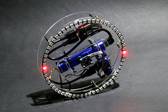
To conclude, here is a short example made with a Yocto-3D-V2, a Yocto-Color-V2,a Micro-USB-Hub-V2 and a few NeoPixel leds:

Our Yocto-3D-V2 test device: compass, artificial horizon and shock detector
The idea is very simple: a small python script runs on the Intel Edison mini-PC. It measures the wheel orientation using the Yocto-3D-V2, and displays a corresponding pattern on the NeoPixel LED ring using the Yocto-Color-V2. Sine the Edison has only one USB port, we used a Micro-USB-Hub-V2 to connect both devices.

The connection diagram
- When the wheel is lying flat, we turn on the LED pointing to the magnetic North.
- When the wheel is standing, we turn on two opposite LEDs showing an artificial horizon
- When the wheel perceives a shock above 2g, we show a quick flash on the ring
Thanks to this small example, we have been able to verify that the compass was calibrating correctly to compensate for hard-iron distortions. The exact same system, when build with the older Yocto-3D, simply does not work: the compass turns with the wheel, because of the magnetic fields generated by the system itself. We have also been able to verify the compass tilt-compensation, as well as proper handling of singularities and the reactivity of the sensor. See by yourself:
We will continue to sell both versions for a while, but the production of the first version will be stopped eventually.


