 Yocto-Meteo owners regularly ask us if Yoctopuce intends to put on the market a sensor to measure wind speed. The problem is that an anemometer contains more mechanics than electronics. We looked at some models available on the market. We concluded that the cheap anemometers were too difficult to hack and that the models designed to be interfaced were way too expensive. We are therefore going to tell you how to create your own anemometer using a Yocto-Knob.
An anemometer is essentially a propeller or a rotor which rotates, driven by the wind. The difficulty resides in determining at which speed it rotates. From this speed, we can deduce the wind speed, more or less empirically. There are several ways to determine the speed of a rotating axle, we selected an optical method: the rotor axle is provided with a perforated disk which is sandwiched between a led and a phototransistor. The phototransistor is conductive each time the led illuminates it. This conductive state can be detected by a Yocto-Knob.
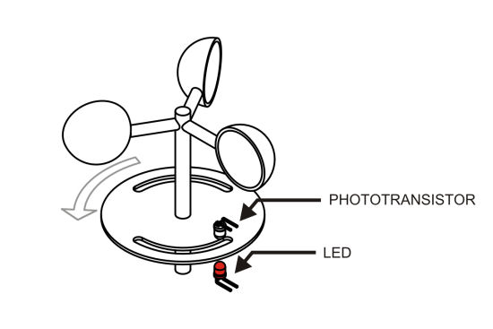
Diagram: the rotor drives a perforated disk which rotates on top of a light sensor
It so happens that the Yocto-Knob has recently inherited a new interesting function with its new firmware: a pulse counter. Each input now has its own monotonous time counter and its own pulse counter. The pulse counter increases by 1 each time the corresponding input changes state. The two counters can be reset to zero simultaneously. Thus, if you connect one of the input of the Yocto-Knob to the phototransistor, it is possible to count the number of perforations that pass in front of the phototransistor in a given time. This is the principle.
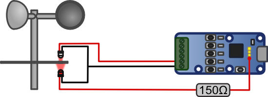
Wiring between the Yocto-Knob and the sensor
At the connection level, the phototransistor is simply connected to input 1 of the Yocto-Knob. However, we must power the led. To do so, we use the 5V provided by USB, we can find it on the pad marked [+] located behind the USB socket of the Yocto-Knob. And we use a 150 Ω resistance connected in series to obtain a power of about 20 mA going through the led. Note that we only need to connect 3 wires to the anemometer, it is safer indeed to keep the Yocto-Knob inside were it is shielded from humidity. The phototransistor is a SFH 310-2/3 from OSRAM and the led is a L7104SRC/J from Kingbright, but many other components would do as well.
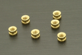
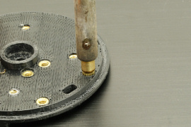
For the implementation, we chose 3D printing to save time. To assemble the pieces together, we used brass inserts that we set with a simple soldering iron with a specific tip. Thus, the different elements can be assembled with simple screws, the result is robust but stays easy to disassemble.
To limit friction, we used special plastic ball bearings which won't be oxidized after the first rain.
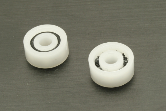
Stainless ball bearings: plastic cage and glass balls
Assembly is relatively simple. When soldered, the led wires and the phototransistor a are embedded in hot glue to prevent potential issues linked to humidity. All the elements are screwed together.
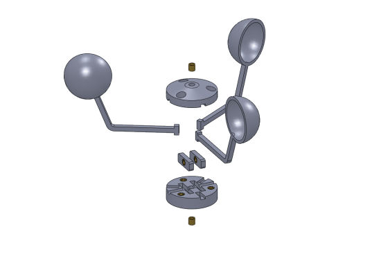
Assembling the rotor
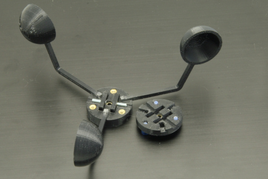
System for securing the rotor on the axle
The rotor axle is a 3mm diameter steel rod. The perforated disk is pushed by force on this axle. To be easily disassembled, the rotor is maintained by two small headless screws perpendicular to the axle. These two screws can be seen on the picture above. Two small rings cut from a brass pipe and pushed by force in the central part of the rotor prevent the rotor from being deformed when the headless screws are tightened. The rotor geometry may appear complex, but this is mostly due to the technical constrains of 3D printing.
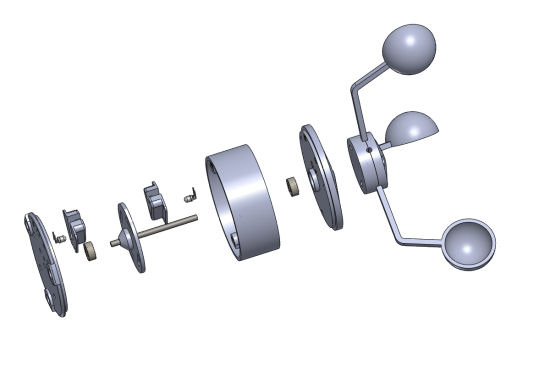
Assembling the body
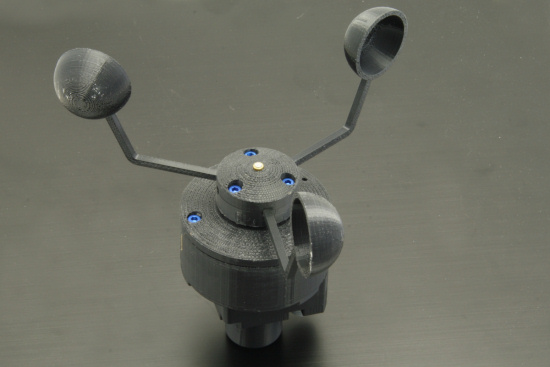
The complete anemometer
The resistance levels detected by the Yocto-Knob depend on the photo-transistor model, LED power and cable length. To make sure the state changes are correctly detected, we can calibrate the matching anButton function using the VirtualHub.
Calibration
At this stage, we have an appliance which rotates when there is wind, generating pulses which a Yocto-Knob can count. The difficulty consists in finding the relation between the frequency of these pulses and the speed of the wind. It is probably possible to compute it, but we selected a more pragmatic approach. The anemometer was fixed on a pole and we took a drive in the car.
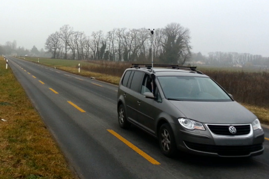
Calibration can be estimated with an empty road and a car :-)
You only need to take a few readings at different speeds to get an idea of this relation. Amusing coincidence, for our anemometer, we are very close to 1 pulse = 1 Km/h under 50 Km/h. At higher speeds, the relation diverges a little, we think the airflow around the anemometer must change. We didn't go above 100 Km/h :-)
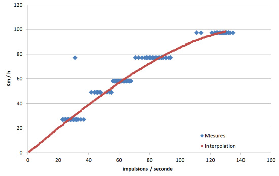
Measure interpolation
In our case, we deduced from all this that the relation between wind speed V in Km/h and the frequency of the pulses f in Hz could be approximated the following way:
V = f - 0.00005*f^2 - 0.000014*f^3
Some advice for the calibration: take each reading for a given car speed in one direction and then in the other, then take the median value to eliminate the effect of the weather wind. Use a GPS to compute the speed of the car, car speed counters systematically overestimate speed. You can use one of the free inputs of the Yocto-Knob to connect a push button to allow you to remotely start the recording of calibration data when the car is stabilized at the desired speed.
Programming
The code to compute the wind speed is relatively trivial. You must retrieve at regular intervals the values of the timer and of the pulse counter, deduce from it the pulse frequency, and then apply the calibration function. Here is a C# example:
// an input named "wind"
YAnButton wind = YAnButton.FindAnButton("wind");
while (true)
{ if (wind.isOnline())
{ long pulse = wind.get_pulseCounter(); // retreive counter values
long time = wind.get_pulseTimer();
if ((pulse > 0) || (time > 5000))
{ // compute frequency
double f = 1000 * pulse / time;
// apply calibration
double windSpeed = f - 0.00005 * f * f - 0.000014 * f * f * f;
// reset both timer and pulse counter
wind.resetCounter();
Console.WriteLine("Speed = "+Math.Round(windSpeed).ToString()+" Km/h");
}
YAPI.Sleep(1000, ref errmsg);
}
}
Conclusion
It is relatively easy to build your own anemometer. We used a 3D printer to save time, but if you don't have a 3D printer, you could probably build your anemometer from easy to find materials such as some PVC pipe and ping-pong balls. But if you like to DIY, we recommend you to take a serious look at 3D printers, they start to become really affordable. The anemometer parts can be downloaded from Thingiverse.
This anemometer is obviously an ultra simple version, many improvements can be brought to it. For example, we could include a heating wire to prevent the anemometer from freezing and jamming in the wintertime.

OK, it's cool, but where does the wind come from?
Well, wind speed: check. Next time, we'll take care of wind direction.


