![]() Following on from our quick tutorial on I2C, we're going to take a closer look at a particular case that often causes problems: the use of long wires for I2C communications. This is particularly true of Yoctopuce sensors that you can split, if you decide to offset the sensor part by several meters.
Following on from our quick tutorial on I2C, we're going to take a closer look at a particular case that often causes problems: the use of long wires for I2C communications. This is particularly true of Yoctopuce sensors that you can split, if you decide to offset the sensor part by several meters.
The I2C bus was originally designed for communication between chips on the same circuit, over distances of a few dozen centimeters. But the apparent robustness of this protocol makes it possible to imagine using it beyond that, typically to position a sensor a few meters away. So where is the limit?
Potential problems
When using a long bus to transmit signals, various problems can affect signal integrity:
- Cable capacitance, which slows down signal edges
- Cable inductance, which causes undershoots
- Signal reflection at the end of the cable (echo)
- External electromagnetic interference (EMI) on the cable
- Side effects of active circuits in reaction to other problems
In practice, on an I2C bus, these problems do not all have the same importance...
Capacitance: an unavoidable problem
Capacitance is the effect of inertia between two side-by-side wires, acting like a capacitor. In the I2C protocol, the falling edges are actively pulled towards ground, and are therefore always quite sharp. Rising edges, on the other hand, are generated by pull-up resistors, which combine with the wires capacitance to form an "RC" circuit:
RC circuit equivalent to a 10m I2C line
The product of wire resistance and capacitance gives the circuit's time constant τ, which determines the time needed to reach 63% of voltage. As capacitance is proportional to wire length, we can see the problem with long wires: the longer the cable, the greater the time constant. For example, given that a 20m cable will typically have a capacitance of 1nF, if we use a pull-up resistor of 4.7kΩ, it will take 4.7μs for the signal to reach 63% of the desired voltage.
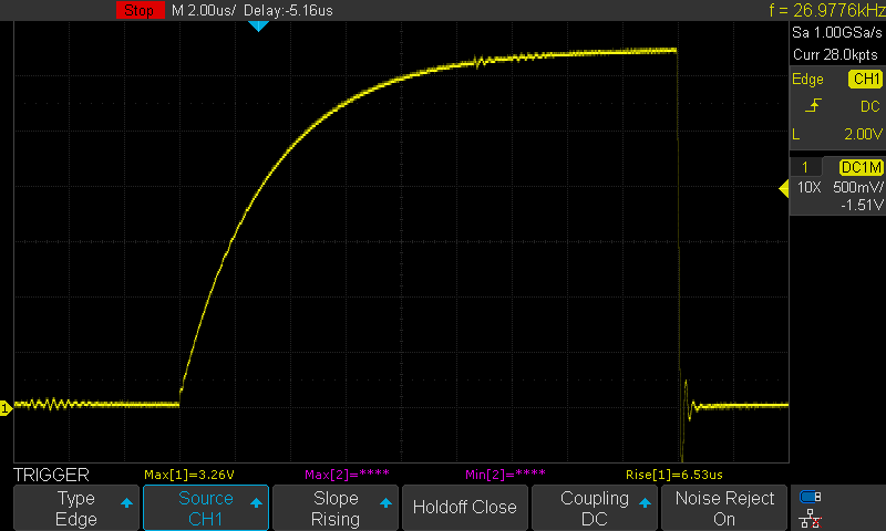
This is why I2C-based Yoctopuce sensors that you can split work at a frequency of around 60 kHz only:

SCL signal capture on a Yocto-Temperature with 10m cable (pull-up 4.7k)
Obviously, if you need to work with an existing device without being able to modify the transmission frequency, the only option left is to reinforce the pull-ups to lower the time constant. This can be done easily by adding a resistor in parallel to the existing pull-ups in the device, between the Vdd and each of the data lines. You can try 2 kΩ or 1 kΩ, but don't go any lower than 690 Ω.
For reliable I2C communication, the frequency should not exceed 1/6τ, so that the signal can reach 95% of the voltage at each half-period. With pull-ups of 1 kΩ, we obtain the following correspondence table between bus length and maximum transmission frequency:
| Bus length | Max. frequency |
|---|---|
| 8 m | 416 kHz |
| 10 m | 333 kHz |
| 20 m | 166 kHz |
| 30 m | 111 kHz |
| 50 m | 67 kHz |
| 75 m | 44 kHz |
| 100 m | 33 kHz |
Inductance: a potential problem
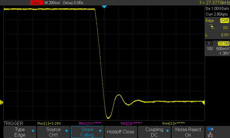
Inductance is another effect of inertia, which opposes rapid variations in the current flowing through a wire. Such variations occur, for example, when one of the circuits pulls a line from the I2C bus to ground. The inductance and capacitance of the wires combine to form an "LC" oscillating circuit, which parasitizes the transmitted signal with a very typical pattern:

Oscillations on the SCL signal on a Yocto-Temperature with 10m cable
For the illustration above, we've greatly enlarged the time scale (one square = 200ns). In reality, the frequency of these oscillations is well above I2C communication speeds, and as long as their amplitude remains relatively low, they are generally not a problem.
What can cause problems, however, is when the signal voltage drops below 0V (below ground): because of the inductance, the voltage continues to drop further than the transmitter requires: this is an undershoot. The longer the cable, the greater the inductance and the greater the undershoot. Above -0.7V, the voltage will discharge into the protection diodes of the receiver circuits, which, depending on the amplitude, may eventually fail, leading to circuit destruction.
For added safety, external protection diodes can be added between the SCL/SDA lines and ground to prevent this from happening.
Reflections: not very significant
When an electrical signal is sent over a pair of wires, it will tend to echo back when it encounters the end, if the end is not terminated with an impedance equivalent to that of the cable. Since the I2C standard relies heavily on specified pull-up resistors, it is generally not physically possible to terminate an I2C bus to avoid echoes.
However, echo is generally not a problem on an I2C bus. In fact, on a 10m cable, signal reflection returns after 100ns, and is low. Actually, we haven't even managed to capture it on an oscilloscope, as it is systematically masked by LC oscillations due to inductance...
Electromagnetic disturbances: not very significant
Electromagnetic disturbances are voltage fluctuations that may spontaneously appear on an electrical wire, induced by the surrounding electromagnetic fields. In a very noisy environment, close to industrial equipment, induced voltages of up to 100mV could be observed on a 10m cable.
But even in this rather extreme case, given the voltage thresholds defined by I2C, such fluctuations could hardly directly affect the interpretation of a bit on the line.
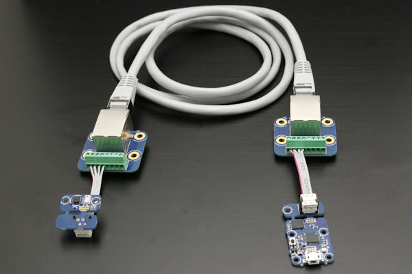
Nevertheless, to avoid any risk, and above all to avoid creating EMI with the I2C bus itself, for transmissions over more than one meter, you can use shielded network cable, made of twisted pairs: use one pair for the GND and SCL wires, and another pair for the VDD and SDA wires. You can do this very easily with a pair of RJ45 adapters.

Extend a Yoctopuce sensor wire easily using RJ45 cable
I2C repeaters: the pitfall
Repeater circuits are sometimes found on an I2C bus. They can be used to change the operating voltage on a section of the bus, to electrically isolate a section of the bus, and even to amplify the signal to transmit it over a greater distance. At first sight, these circuits are very useful, but they hide a trap that is less well known and more perfidious than the problems seen above...
A repeater acts as a bridge between two I2C bus segments. As I2C lines are bidirectional, a repeater must monitor the I2C lines on both segments, and when it detects that a line is dropping on side A, it must drop it on side B. When the line on side A rises, it must drop it on the other side. When the A-side line rises, it releases the B-side line.
How an I2C repeater works, in this example from A to B
If in the meantime another chip on side B holds the line down, as can naturally happen during I2C communication, then the repeater must lower the line on side A again immediately, before the circuit on side A has had time to realize that it has begun to rise. For this reason, repeaters must react to bus changes with very tight time tolerances, even when the transmission frequency is relatively low.
Special case requiring rapid feedback from B to A
But what happens if the line has a high capacitance, and rises more slowly than usual? When the repeater releases the line, if it doesn't come up fast enough, the repeater will consider that another node is pulling it down. It will then pull the line down on the other side, causing a transmission error.
Confusion caused by a high-capacitance line
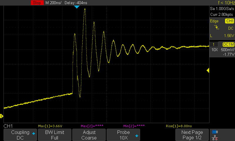
Here's an example of what can happen if you offset the Yocto-Meteo-V2 's breakaway sensor by 10m or more:

Undesired effect of the I2C level changer in the Yocto-Meteo-V2 sensor
The slightly too slow rise of the SCL line causes hesitation in the repeater/level switch, which creates a large "LC" oscillation crossing the voltage thresholds defined by I2C. The repeater does not transmit this hesitation to the other side of the bus it controls, but it does affect the other sensors on the bus by creating false clock pulses.
So unfortunately, the repeater you might hope to rely on to manage a long bus can be counter-productive on other nodes, due to its side effects. This is particularly the case in star bus configurations, where the parallel arrangement of several repeaters represents a major risk of mutual interference if they have not been selected and tested with full knowledge of the facts.
Practical solutions
In practical terms, to overcome these problems, you need to proceed methodically:
- Get a pair of RJ45 adapters (RJ45-Adapter or equivalent) to mount on both sides of your I2C bus, and network cables of various lengths (1m, 2m, 5m, 10m, 20m). This way you can easily repeat experiments with different bus lengths.
- Get 3kΩ, 2kΩ, 1kΩ and 690Ω wire resistors (one pair of each).
- Start by reproducing a simple working state, without adding a pull-up, with a 1m cable, and check that the device works properly.
- Gradually increase the length of the bus, and check whether device operation is affected. If you're using a Yoctopuce sensor, open the module's log window: it shows all I2C communication errors and will therefore enable you to detect the first errors leading to retransmissions, even before they are clearly apparent when using the module.
- When the first transmission error appears, try adding a pair of 3kΩ pull-up resistors. You can insert them directly into the RJ45 adapter terminal block (on the powered side of the bus, in parallel with the existing pull-ups). If that's not enough, replace them with 2kΩ or 1kΩ
- Continue to lengthen the bus and lower the pull-up values to find your device's usable limit.
If you have the possibility of slowing down the communication speed, this is desirable anyway. But of course, this isn't always possible if you didn't design the device yourself. If you're using a Yocto-I2C to communicate on the I2C bus, you can easily change the communication speed in the module's configuration. Note that below 62 kHz, the Yocto-I2C switches to bit-banging mode, where it no longer monitors each transition on the bus, but reads the state of the lines after each half-period. It will therefore be more robust to any hesitations of I2C repeaters if you choose to work at low speeds, such as 10 kHz or even 1 kHz.
In the end, if you can't find a solution to lengthen your bus with this method, you still have the option of connecting an oscilloscope: seeing the signal always helps you understand what's going on. And if the problem seems unsolvable, ask yourself whether I2C is really the right protocol for your application. RS485 and SDI-12 are clearly better suited to transmitting information over long distances.


