![]() You may have noticed that we have removed the Yocto-Motor-DC from our assortment. Some components were no longer available, and since we sold very few of them, replacing them with an exactly equivalent module was not justified. But as we will show you below, this does not mean that you can no longer drive a DC motor with Yoctopuce modules.
You may have noticed that we have removed the Yocto-Motor-DC from our assortment. Some components were no longer available, and since we sold very few of them, replacing them with an exactly equivalent module was not justified. But as we will show you below, this does not mean that you can no longer drive a DC motor with Yoctopuce modules.
This project was realized by Ariel, an intern at Yoctopuce to whom we had entrusted the task of checking if it was easy to drive a DC motor with the modules currently available. The goal was to create a simple drive system for a motorized carriage moving on a rail. The carriage is driven by a reducted DC motor, directly connected to a threaded rod. For this drive system we use:
- A RC motor controller to drive the motor
- A Yocto-Servo to drive the RC motor controller
- A Yocto-PWM-Rx to measure the position of the carriage
- A Yocto-PowerRelay-V3 to manage emergency stops
And for the control panel with physical keys:
Motorized rail
For this project we have used a motorized rail from Open Builds:

Motorized rail purchased a few years ago from Open Builds
The rail has a motor that drives a threaded rod in the center axis of the carriage, which allows movement along the entire length. We replaced the original stepper motor with a DC motor with a 34:1 reduction, which includes a Hall effect sensor that provides accurate measurement of motion by quadrature encoding.

Reducted DC motor mounting with quadrature encoder
Motor Control
The motor is controlled by a Hobbywing RC motor controller. We drive the controller with one of the five channels of the Yocto-Servo. There is one particularity of RC motor controllers: they usually include a safety feature to avoid breaking mechanics by a sudden switch from one direction to the other. Once a direction is engaged, the controller requires a full stop before engaging in the opposite direction. But you can usually find in the controller's documentation how to disable this safety feature to ensure direct control of the motor by the Yocto-Servo.

The RC motor controller used to drive the DC motor
The Hall sensor on the motor produces a quadrature signal that the Yocto-PWM-Rx can automatically decode to provide an accurate measurement of the distance the carriage has traveled.

Power supply
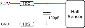
The motor we have chosen has a recommended operating voltage of 6V but can also withstand higher voltages, at the risk of accelerated wear. The drive requires 7.2V, so we chose a single 7.2V supply for the entire system, including the power supply for the Hall sensor on the motor.
The motor is an inductive load and can generate significant voltage spikes on our power supply. Here is a measurement of the disturbance observed when the motor is switched:
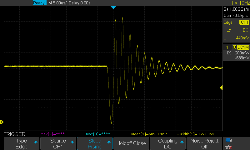
We have therefore taken the precaution of installing an RC filter on the Hall effect sensor power supply to avoid any disturbance on the measurements of the position of the carriage.
Control panel
For the user interface, we chose to reuse an existing control panel with 6 function buttons and 2 joysticks, connected to a Yocto-MaxiKnob.

Control panel with physical keys, connected to a Yocto-MaxiKnob
End of travel handling
To protect the mechanical system and the motor, we integrated end of travel switches in the rail. The two buttons are fixed at each end of the rail with small PMMA plates. The buttons are aligned on the side of the carriage body so that the carriage can correctly press them in case of end of travel.
We used switches with double output, allowing an immediate hardware disconnection of the motor and a signaling of the event to the control software via the Yocto-MaxiKnob. Once the cut-off situation is detected by the software, it is able to deactivate the hardware safety (override function) using a Yocto-PowerRelay-V3.

Installing the end of travel switches
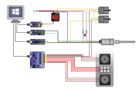
After a little wiring session on all the peripherals, here is the complete schematic of the project:
Software
The control software is written in C#. For maximum reactivity, all the sensors are read by value change callbacks. The control of the system is managed by a state machine.
As the rail does not have an absolute encoder but only a distance measurement, an origin search has to be performed at system startup.
The first command sends the carriage reasonably fast in the direction of the starting end of travel switch. Once there, the next command stops the motor and slowly moves it out of the stop. At this point, the software resets the position counter of the Yocto-PWM-Rx module using the command.set_currentValue(). A distance of 500 is originally used to avoid that the movements to the zero position press the carriage against the limit switch.
{
Console.Clear();
Console.SetCursorPosition(0, 0);
Console.WriteLine("CALIBRATING, PLEASE WAIT...");
relay.set_state(YRelay.STATE_B);
motorMove.move(-666, 10);
do
{
YAPI.Sleep(2, ref errmsg);
} while (dangerStart == false);
motorMove.move(0, 0);
YAPI.Sleep(100, ref errmsg);
Console.WriteLine("End of course found");
motorMove.move(250, 10);
do
{
YAPI.Sleep(2, ref errmsg);
} while (dangerStart == true);
motorMove.move(0, 0);
Console.WriteLine("Moved out of end condition");
YAPI.Sleep(150, ref errmsg);
railRealPosition.set_currentValue(500);
quadroPosition = 500;
YAPI.Sleep(50, ref errmsg);
Console.WriteLine("Origin set");
motorMove.move(300, 0);
YAPI.Sleep(300, ref errmsg);
motorMove.move(0, 0);
relay.set_state(YRelay.STATE_A);
Console.Clear();
}
We encountered a constraint with the dual buttons we chose. They can end up in an ambiguous state when the carriage touches the button: the safety circuit that cuts the motor opens while the logical position sent to the software is not yet closed. To remedy this concern, we use our Yocto-PowerRelay-V3 in the function to make sure that the motor is free to move away from the button, and we send a short pulse to make sure that the motor gets out of this ambiguous interval. The relay is then opened so that the motor is again protected by the end of travel switch.
Sending the carriage to a specific position
A setPosition(double value) function is responsible for sending the carriage to a precise position on the rail. The ideal control solution is of course a PID, but for this small example we initially settled for a linear setpoint displacement control and a speed proportional to the error between the setpoint and the actual position.
We then calculated the error between this setpoint and the actual position. With these data, the motor position correction command is in place. A few tests allowed us to find the minimum command value to put the carriage in motion.
{
ulong deltaTime;
ulong startTime, endTime, realTime;
int startPosition, endPosition, realPosition, cmd;
double error, order;
startPosition = quadroPosition;
endPosition = (int)(MAX_POSITION * place);
startTime = YAPI.GetTickCount();
endTime = (startTime + (ulong)(endPosition / SPEED));
do {
showSystemInfo();
realTime = YAPI.GetTickCount();
realPosition = (int)quadroPosition;
deltaTime = (YAPI.GetTickCount() - startTime);
if (deltaTime >= (ulong)(endTime - startTime)) {
order = endPosition;
} else {
order = startPosition + ((endPosition - startPosition) *
((double)deltaTime / (endTime - startTime)));
}
error = order - realPosition;
cmd = (int)error / 8;
if (cmd >= MAXIMUM_SPEED) {
cmd = MAXIMUM_SPEED;
} else if (cmd <= -MAXIMUM_SPEED) {
cmd = -MAXIMUM_SPEED;
}
if (cmd >= 0 && cmd <= MINIMUM_SPEED_L) {
cmd = MINIMUM_SPEED_L;
} else if (cmd <= 0 && cmd >= -MINIMUM_SPEED_R) {
cmd = -MINIMUM_SPEED_R;
}
motorMove.move(cmd, 10);
YAPI.Sleep(3, ref errmsg);
} while ((Math.Abs(realPosition - endPosition) > POSITION_TOLERANCE_VALUE)
&& (systemMode != WARNING));
motorMove.move(0, 0);
}
We set a different value as a preset for each button on the control panel in order to have several markers on the rail: F1 = 0%, F2 = 25%, F3 = 50%, F4 = 75%, F5 = 100%.
With this rather trivial servoing algorithm, we arrive at an accuracy of ~0.5mm in normal movements, and ~1mm towards the initial end of travel switch, because due to the rail assembly, the motor has more mechanical difficulty reaching this position, and we had to use different minimum speeds depending on the desired travel direction so that the carriage could still reach its set point. A full PID would certainly improve the accuracy even further along the entire length.
Conclusion
This project has shown you how to drive a DC motor with very standard hardware, and the interest of using an angular sensor with a quadrature encoder to precisely measure the displacements of such a motor.

