 Following last week's article, here is a small real-world application using HTTP callbacks to drive Yoctopuce modules through a NAT filter. We will use here a Raspberry Pi because it's cheap and we don't need too much out of it: only to run a VirtualHub to generate periodic callbacks.
The application: Remote light control
The selected application is to control lighting remotely. This may serve to simulate a presence at home to deter prowlers, but obviously you can transpose this example to remotely commute almost any appliance at home (turn your computer on remotely, preheat the coffee machine, etc.).
To commute a lamp or another appliance, the classical method is naturally the Yocto-PowerRelay. Simple and effective, you can even hide it directly inside a strip:
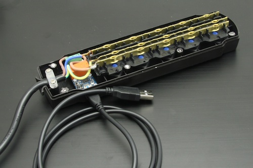
The trivial version: a relay hidden in a strip
If you wan to avoid tinkering with 220V, or if you want to control an appliance which is not directly within reach of a cable, it is sometimes easier to drive a remote control. For this example, we bought a set of three radio-controlled sockets in a supermarket (for slightly less than EUR 50):
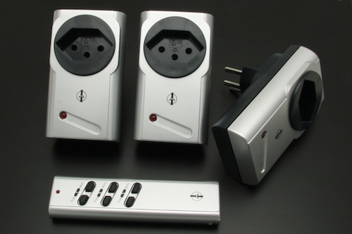
A set of radio-controlled sockets bought in a supermarket
Keys on remote controls are generally made on the Chiclet keyboard model: a carbon layer attached to the bottom of the rubber keys puts into contact two tracks of the remote control printed circuit when the key is pressed (for more details, consult the Wikipedia page). We can simulate a key press by closing the same contacts with a simple relay. It's not easy to solder a wire directly on the printed circuit tracks without damaging the remote control. But if we follow the tracks and use an electric tester, we can easily locate on which printed circuit pad each key is wired, and find an easier location to solder a wire.


The inside of a "Chiclet" key remote control
We decided to simply connect all the contact points to an inline connector strip which we inserted in the bottom side of the remote control. Thus, the remote control stays easy to use manually, but we can put it in a docking station to pilot it automatically with relays.
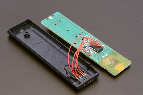
The open remote control, with our remote control connector, which won't be noticed.
Our docking station is very simple. It contains only two Yocto-Relay, (each one with a pair of relays), themselves connected to a Micro-Hub to use only one USB port. We must simply take care to wire the relays on the contacts in a way enabling us to reproduce how pressure on the remote control keys close the contacts.

Wiring diagram for connecting the remote control with the relays.
Everything is neatly assembled into a YoctoBox-MaxiRelay-Black, with a slightly modified front to allow the remote control to stand upright. The docking station is connected to the Raspberry Pi with a simple USB cable, like we did with our USB strip.
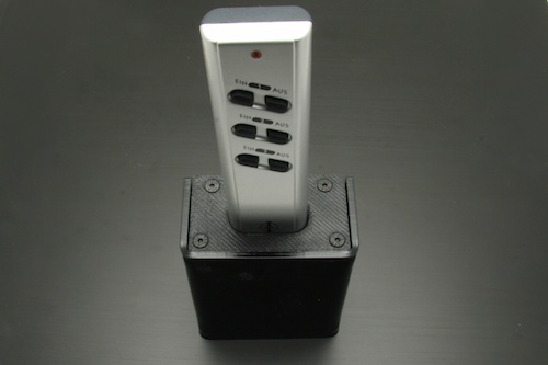
Our 'Yocto-docking station' for socket remote control
To simulate the keys of the remote control, we must close the contacts only temporarily (pulse). Depending on the diagram above, the code to use to connect the contact controlling socket 2 to the On contact is the following:
$out2 = yFindRelay("Out2");
$state->set_output(Y_OUTPUT_ON); // select the "On" contact
$out2->pulse(500); // Connecting with output 2
A web interface to drive relays
To make your work easier, we have prepared a small PHP example including a PHP control page and a web command interface (based on jQuery and compatible with mobile phones).
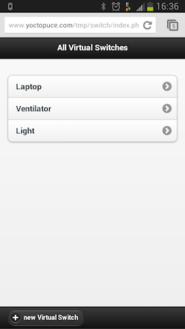
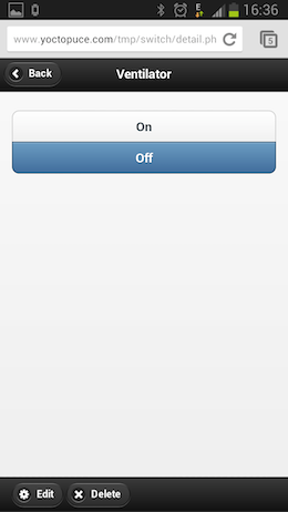
This web application allows you to define virtual switches which are going to activate one or more real relays. As it's the VirtualHub which decides when it contacts our PHP script, the web application must save in a file (or in a database) the actions to be performed next time our callback script is called.
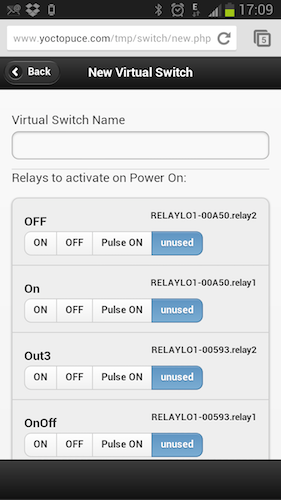
Logical switch configuration page
The only page using the API is the callback.php page which, on top of initializing the API in callback mode, has two tasks to perform:
First, we save in a file the list of connected relays. The aim is to have a list of the connected relays so that when configuring we don't have to remember the serial number of the relay which is connected.
Second, we apply the necessary actions on the relays. To do this, we load the files containing the actions to be run and we call the relay pulse or set_output methods.
include('yocto_relay.php');
// Uses explicit error handling rather than exceptions
yDisableExceptions();
// Sets up the API to use the VirtualHub on local machine
$errmsg = "";
if(yRegisterHub('callback',$errmsg) != YAPI_SUCCESS) {
logtofile("Unable to start the API in callback mode ($errmsg)");
die();
}
...
...
// create an array of all connected Relay ( we do not use it
// no but if will be usefull when the user will configure his
// VirtualSwitch)
$detected_relay= LoadDetectedRelays();
$yrelay = yFirstRelay();
while($yrelay!=null){
$detected_relay[$yrelay->get_hardwareId()] = new Relay($yrelay);
$yrelay = $yrelay->nextRelay();
}
SaveDetectedRelays($detected_relay);
// loads all VirtualSwitch that need to be updated
$all_vswitches = LoadVirtualSwitchesToUpdate();
foreach($all_vswitches as $name => $virtual_switch) {
// retrieves the list of all physical relay of current
// Virtual Switch to update
if($virtual_switch->isOnNow()){
$relay_to_update =$virtual_switch->getRelaysForState('on');
} else {
$relay_to_update =$virtual_switch->getRelaysForState('off');
}
foreach ($relay_to_update as $hwid => $action) {
//applies to the Yocto-Relay the corresponding action
$yrelay = yFindRelay($hwid);
if(!$yrelay->isOnline()){
logtofile("$hwid is not online");
}
switch($action){
case 'stateOn':
$yrelay->set_output(Y_OUTPUT_ON);
break;
case 'stateOff':
$yrelay->set_output(Y_OUTPUT_OFF);
break;
case 'pulse':
$yrelay->pulse(500);
break;
default:
logtofile("Unspported action:".$action);
}
}
}
The complete source code is available on GitHub. For a more universal and professional solution, you should add the possibility to program different day/night cycles and a randomization function to simulate a presence. We have tried to keep the code as simple as possible to illustrate this new working mode.


