![]() If you use your Windows computer to listen to music while you are working and if, depending on the circumstances, you listen to this music with a Bluetooth headset or external speakers, you might have noticed that switching from one mode to the other is somewhat tedious. One must possibly unlock the screen saver, then open the sound interface and select the output device in a drop-down list. Why not build a physical interface which would be easier to use?
If you use your Windows computer to listen to music while you are working and if, depending on the circumstances, you listen to this music with a Bluetooth headset or external speakers, you might have noticed that switching from one mode to the other is somewhat tedious. One must possibly unlock the screen saver, then open the sound interface and select the output device in a drop-down list. Why not build a physical interface which would be easier to use?
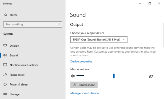
We would like the same thing, but with real buttons
In fact, it's not fundamentally difficult to build, but to do it well, it requires quite a lot of work.
Hardware
The idea is to have a small box connected to a PoE Ethernet cable, which would allow us to put it just about anywhere, as long as there is a Ethernet socket nearby. We'd like a rotary knob to select the output, a screen to display the name of the active output, and while we are at it, another knob to control the volume.
We are therefore going to use:
- A YoctoHub-Ethernet for the network part
- A Yocto-MiniDisplay for the screen
- A Yocto-MaxiKnob to manage the knobs

We need a YoctoHub-Ethernet, a Yocto-MiniDisplay and a Yocto-Maxiknob
For the knobs, we are going to use quadrature encoders. We selected two different ones:
- a E33-VT610-M03T from Elma, which clicks nicely when you turn it, to select the audio output.
- a PEC11R-4215F-S0024 from Bourns, easier to turn, for the volume.
As these two encoders have a push-button feature, we are going to use that of the volume knob for a "Mute" function.
We are also going to use the RGB output of the Yocto-MaxiKnob to drive a world-semi WS2812D-F5 led which indicates whether the box is currently working, i.e. if the software driving it is active.
For the enclosure, we selected a Hammond 1455k120BU enclosure. Instead of using the original front panels and fastening system, we tapped the holes in the case and cut new front panels out of 1.5 mm aluminum that we fasten with M4 screws with (very) flat heads. We cut a small window for the screen and the led in 2mm acrylic glass with a CNC milling machine. Encoders are mounted on the front panel. The knobs themselves were manufactured with a 3D resin printer.

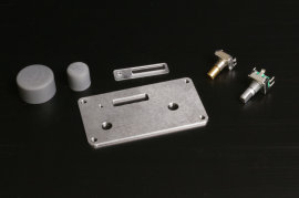
The enclosure elements and the front panel
Wiring and assembling
Wiring is really trivial, you only need to connect all the elements together.

Interconnecting the different elements
To obtain a clean assembly, the different elements are mounted on an acrylic glass pane that slides into the enclosure. We had to split the Yocto-MiniDisplay in two to be able to set the screen part right in the center of the front window. The modules are interconnected with 1.27-1.27-11 cables and the knobs are connected to the Yocto-MaxiKnob with Dupont wires.
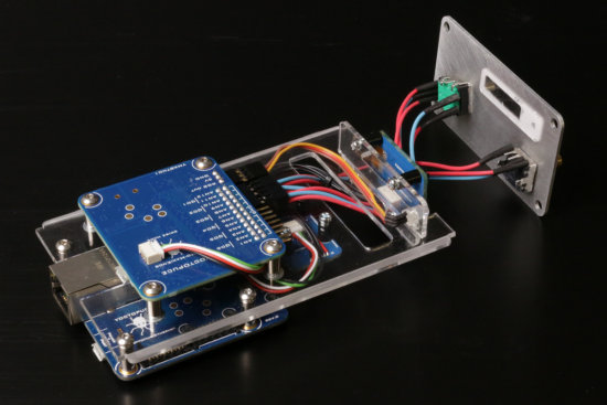
The fully assembled electronics
When the front panel and the knobs are painted, we obtain a rather professional looking small enclosure.
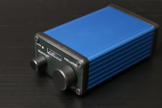
Not bad, not bad...
Software
Coding the software part clearly required more time than building the hardware. We decided to code it in C++ because this enabled us to create an executable without any dependency.
The general principle
The encoders are managed with valueCallback callbacks. The call to these callbacks acts on Windows AudioEndPoint configurations. In parallel other callbacks are called each time there is a modification linked to an AudioEndPoint. These callbacks trigger a refresh of the enclosure display. With this technique, the display is always updated, whether the modifications are performed on the blue box, from the Windows interface, or even from the keyboard.
Managing the led
Obviously, the box works only if the software driving it is running. To indicate whether the box is active, we configured the RGB led for it to be red when powering on. The software creates an animation which switches the led to green during 15 seconds then jumps to another animation which switches the led to red. Every 13 seconds, the software reinitializes the green animation. Thus, the led stays green as long as the software is running, but switches to red a few seconds after the software stops. We already used this technique in our network failure detector.
Execution
Obviously, we didn't want to have to launch the executable each time that the computer boots. So we made sure that the software could run both in command line mode and in Service mode.
You can download the executable and its source code here. It's use is relatively simple, you can run it with the following commands:
- -help: displays help
- -install: installs the exe file as a service named YAudioOutputSwitcher
- -uninstall: uninstalls the service
- -start: starts the service
- -stop: stops the service
- -hub ip: saves the IP adress of the YoctoHub-Ethernet and launches the execution
If you run it without command, the software starts with the latest registered hub address.
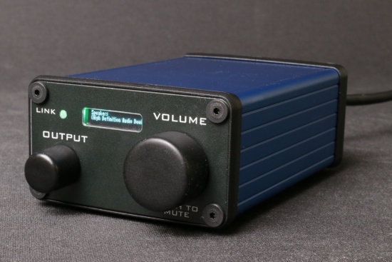
It works
Conclusion
We are very happy with our lillte blue box which enables us to select the audio output and to adjust the volume of a computer by turning two knobs. We used a YoctoHub-Ethernet because we have plenty of PoE networks sockets at Yoctopuce, but we could have easily built a Wifi version with a YoctoHub-Wireless-n. In use, the only small defect of this little DIY project is the size of the screen: you have to squint a little to read it, but a Yocto-Display would have been difficult to fit in so small an enclosure.


