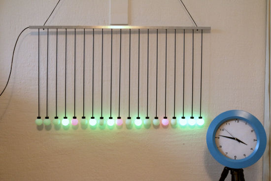
![]() This week, we present a small and quite simple DIY project based on the fact that white ping-pong balls make excellent light diffusers. We built a kind of multicolor chandelier, that you can drive through the Internet and which is PoE powered.
This week, we present a small and quite simple DIY project based on the fact that white ping-pong balls make excellent light diffusers. We built a kind of multicolor chandelier, that you can drive through the Internet and which is PoE powered.
The idea is to use ping-pong balls and to put an RGB led in each of these balls. We selected NEOPIXEL leds from Adafruit: They are already soldered on a tiny PCB and you can buy them in bulk for a reasonable price. To drive these leds, we use a Yocto-Color-V2 enabling us to not only assign a color independently to each led, but also to play completely autonomous animations. Psychedelic light effect coming.
![]()
The raw material, NEOPIXEL leds and ping-pong balls
Building stage
We wanted thus to build a ribambelle of small luminous balls at the end of well aligned rigid rods.
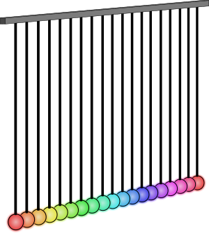
We wanted to build something looking more or less like this
To do so, on top of the leds and the ping-pong balls, we used:
- 4mm carbon tubes, available in good modeling stores
- 3mm plywood sheet
- One meter of U-shaped aluminum profile
- Beads with a 4mm hole and which fit in the profile
- Electric wire that can hold at least 1A
- Electric wires that are small enough to put 4 threads into the carbon tubes
- Epoxy adhesive
The bulbs
To create our "bulbs", we started by cutting three rings in the plywood. We glued them together and painted them black. This makes a kind of hood in which each led is inserted. One could probably use bottle caps instead.
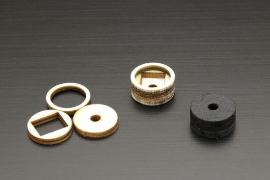
Building the small hoods
Then, we soldered four small wires on the +,GND,In, and out pads of each led.
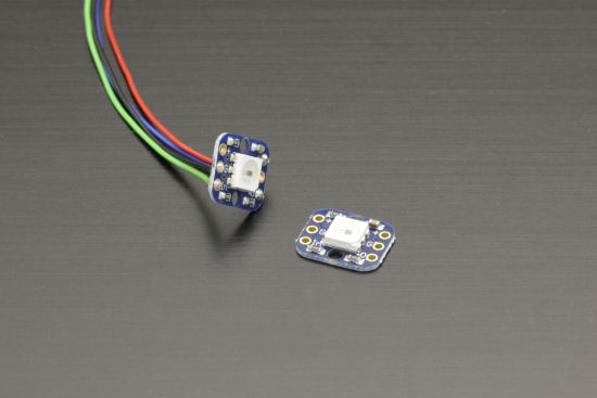
We solder wires on each led
We make the wires go through the carbon rod. As they fit tightly, the easiest is to strip the end of the wire, to twist them, and to solder them at the end of a rigid wire. Then you make the rigid wire go first through the carbon rod and then to pull it so that the other 4 wires follow. The led is then at the end of the carbon tube.
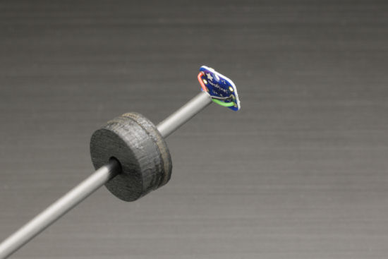
We make the wires go through the carbon rod
Then, with a Dremel and a milling cutter, we make a big hole in each of the ping-pong balls. This hole must be larger than the led but smaller that the hood diameter. Moreover, if you center it on the joint plane of the ball, it is then easier to orient all the balls the same way. Indeed, the joint remains visible by transparency.

Drilling holes in the ping-pong balls
After checking that the led still worked, we finally glued together the carbon tube, the hood, and the ball with Epoxy adhesive. To make sure that the rod and the ball are correctly aligned, we made a small centering device which holds everything together while the glue dries.


Gluing and testing
The support
To build the support, we drilled holes at a regular interval in the aluminum profile. The hole diameter is slightly larger than that of the rods: 5mm so that the rod can hover in the hole.
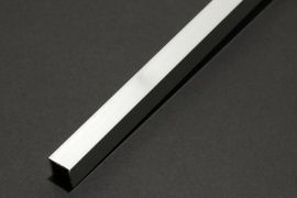
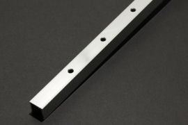
Aluminium profile; drilling.
Then we put a rod in each of the holes and we ended each rod with a bead. Thus, when the whole is vertical, each rod stays almost free to orient itself as it wants to.


The beads lock the rods
We then wired all the rods by soldering the wires together. The + and GND are soldered to two wider wires which run in the inside of the profile. The IN and OUT are chained. Frankly, it's the most fastidious and less amusing part. If we need to make another, we'll have a PCB built that we'll put at the bottom of the profile and we'll solder the wires directly on it. It will be more expensive, but it will be infinitely easier and cleaner.
![]()
Wiring diagram
When the system is hanging, we noticed that the ball alignment, while reasonable, wasn't perfect, and this despite the bead trick. So we built a template to align the balls and when in place we immobilized the rods by pouring Epoxy adhesive into the profile. A piece of advice: check that all the leds work before you glue everything for good.
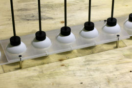

Immobilizing the balls and gluing the rods
When the glue is dry, we remove the template and the balls have kept their beautiful alignment.
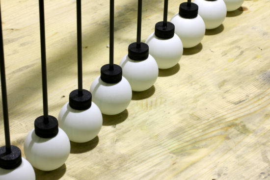
Lined up as if on parade
The controller
The leds are driven by a Yocto-Color-V2, itself driven by a YoctoHub-Ethernet. We also used a Yocto-Light-V2 to measure the ambient light and to be able to adjust the chandelier luminosity accordingly. To have something clean, we used DipTrace to manufacture a PCB that we used to interconnect the three modules. And we put everything in a nice aluminium enclosure.
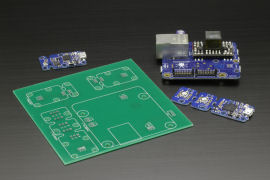
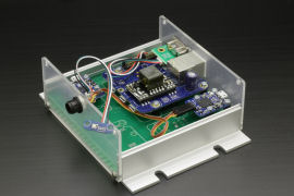
The controller
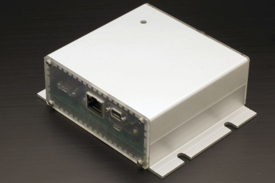
So we ended up with 19 lighted ping-pong balls, that we can power and control through the Internet. We can even program autonomous interaction remotely using the Yocto-Color-V2 animation system.
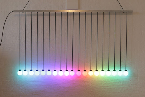
The system, finished
As YoctoHub-Ethernet supports PoE, there is no need for a distinct power source: the whole system is powered by the Ethernet cable.
Application: A BCD clock
To tell you everything, this small DIY project is not intended only for nice light effects. We intend to use it as a BCD clock. Indeed, with 19 balls, we can make four groups of 4 balls each, separated by a single ball. It's quite enough to display in binary the four digits corresponding to the hours and the minutes.
Application: a BCD clock
Obviously, displaying the time can't be done autonomously. But using the HTTP callback HTTP system of the YoctoHub-Ethernet, a simple PHP script can do the trick:
include("yocto_api.php");
include("yocto_colorledcluster.php");
include("yocto_lightsensor.php");
$errmsg='';
date_default_timezone_set('Europe/Paris');
if (yregisterhub('callback',$errmsg)!=YAPI_SUCCESS) die($errmsg);
$leds = yFirstColorLedCluster();
if (is_null($leds)) die('No led cluster');
$sensor = yFirstLightSensor();
if (is_null($sensor)) die('No light sensor');
$l = intVal($sensor->get_currentValue() / 2);
$l = max( 0x10, min( 0x80,$l ));
$now = Date("Hi");
for ($i=0;$i<19;$i++)
$buffer[$i]=0x008000 | $l;
for ($i=0;$i<4;$i++)
{$digit = ord($now[$i])-48;
for ($j=0;$j<4;$j++)
$buffer[$i*5+$j]=($digit&(1<<(3-$j)))>0?0x40FF00|$l:0x40FF00|($l>>4);
}
for ($i=0;$i<19;$i++)
$leds->hsl_move($i,1,$buffer[$i],900);
Print('done.');
?>
As a conclusion, here is a short video of the working system.


