![]() The application that we discuss this week answers an actual problem that we encountered this Summer: how to replace an old float level regulator for a swimming pool, impossible to repair, with an alternative solution which fits in the same small sealed cavity. The main aim is to avoid expensive replacement work. If at the same time we can increase our control on the pool water consumption, it's always a bonus...
The application that we discuss this week answers an actual problem that we encountered this Summer: how to replace an old float level regulator for a swimming pool, impossible to repair, with an alternative solution which fits in the same small sealed cavity. The main aim is to avoid expensive replacement work. If at the same time we can increase our control on the pool water consumption, it's always a bonus...
Principle
The pre-existing float regulation system is based on the principle of communicating vessels: in a cavity connected to the pool, a float opens and closes a tap that brings water, following the same principle as in the tank of flush toilets. When the float is too low, the tap opens and when it is up again the tap closes.
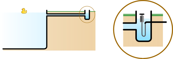
Diagram of the pool water level regulation
The system is so simple that it can work for years... but when it has permanently seized up, there isn't necessarily a replacement model that fits into the same small cavity. Our idea is therefore to replace the float tap with a small solenoid sprinkler valve, that we drive with Yoctopuce modules.
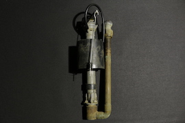
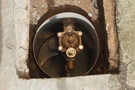
Before: a seized-up float valve - after: a solenoid sprinkler valve
To measure the water level, we use our tiny laser telemeter, the Yocto-RangeFinder. To open the valve, we use a simple Yocto-PowerRelay. And to drive everything remotely, we connect them to a YoctoHub-Ethernet, with a Power-over-Ethernet (PoE) power supply.

Diagram of the electronic regulation system
Implementation
The difficulty of this project is that not only it is an outside project, but the electronics needs to be located in a potentially submerged zone, for example in case of incorrect manipulations of the valve. Everything therefore needs to be waterproof, up to the IP67 standard.
The most exposed part is naturally the laser telemeter, as it must directly measure the distance to the water surface. We don't have a standard waterproof enclosure for the Yocto-RangeFinder sensor, but we found a technique which works very well to protect it from submersion: you can mold it into clear casting Epoxy resin, such as Super SAP CCR. If you take care to have only a thin layer before the sensor, and without any bubble, the telemeter works perfectly. If you add threaded inserts in the mold, you obtain a plate that you can then fix with a joint on a waterproof enclosure for example:
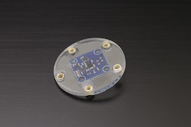
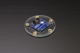
The Yocto-RangeFinder distance sensor made waterproof
We assembled the YoctoHub-Ethernet and the two modules together with threaded spacers, a couple of Board2Board-127 connectors, and a 1.27-1.27-11 cable to form a compact block:
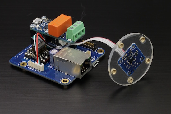
...
Everything fits perfectly in a Hammond 1550WD metal IP67 enclosure, which has moreover the advantage of naturally dissipating the heat generated by the electronics. By carefully drilling a few openings in the enclosure, we could add connectors that are waterproof too. We used a RJ45 waterproof set manufactured by Amphenol (series RJF 544) and 4-pole connectors manufactured by Binder (series 713), which all proved easy to assemble. To fix the modules in the enclosure, we used a well tested technique described in this post.
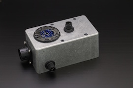
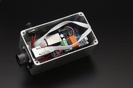
The home-made regulation controller
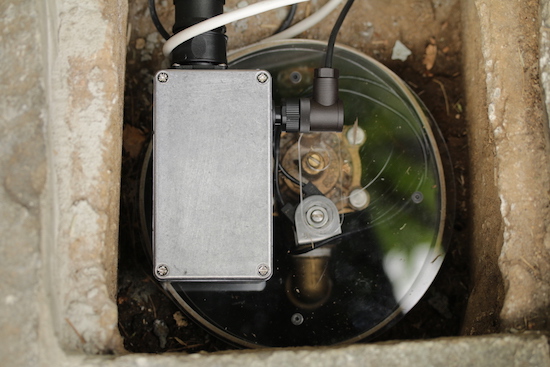
The complete system, located on top of the valve
Control logic
A first manual test allowed us to check that the telemeter works well to detect the water level: from a distance of about 175mm, when we opened the valve, we saw the distance decrease - and therefore the water level increase in the cavity:
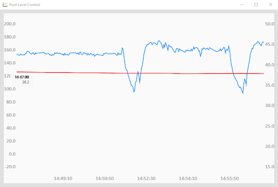
Telemeter measures, when opening the valve shortly
Interesting point: shortly after the closing of the solenoid, the water level in the cavity goes down below the initial level for a moment. This shows the pumping effect produced by the inertia of water circulating in the pipe between the cavity and the swimming pool. That effect later produces a few oscillations, before stabilization occurs.
The basic logic consists therefore in opening the valve by pulses of a few seconds when the water level is deemed too low, waiting between pulses for the water level to go down.
To avoid the valve staying open by accident, the relay is always switched with the pulse(duration) function rather that switching in completely. Thus, even if the control programm would stop or lose communication, the valve is automatically closed after a few seconds.
Likewise, to avoid bringing water without limit in case of telemeter measure error, after each series of 50 pulses, we wait until the water level stabilizes and we check that the pool average water level has indeed increased. If it is the case, we go on filling the pool if need be. Otherwise, we trigger an alarm in order for a user to check whether the system is out of order or whether the pool is leaking...
We can program the system to not fill the pool during some time slots, for example when the automatic sprinkler system is working and water pressure must remain maximal.
Finally, we keep the history of performed water intakes. By performing an initial calibration through the water meter, this allows us to graph the water quantity that is needed during the year in the pool, depending on the temperature and on the use of the pool.


