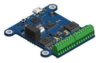
The Yocto-Maxi-IO-V2 device provides 8 digital I/O, electrically isolated from the USB bus. Each I/O bit can be configured individually as a simple input, an open-drain input (internal pull-up), a TTL/CMOS-like output, or an open-drain output (open collector). Without external power source, each I/O pin can receive or produce a digital signal at 3V or 5V levels (low current). With an external power source, the device can work with voltages up to 28V and deliver up to 250mA per channel, which makes it possible to drive small relays for instance. If you need 4 channels only, you can use the Yocto-IO instead.
This device can be connected directly to an Ethernet network using a YoctoHub-Ethernet, to a WiFi network using a YoctoHub-Wireless-n and to a GSM network using a YoctoHub-GSM.
USB cables and enclosures to be ordered separately.
I am trying to use channel 0 as input from another output. The input signal has low value of 1V and high as 3.3V. When I connect it to maxi-io-v2, the input voltage drops significantly in that it always read it as logic LOW. How does the maxi-io-v2 input work. How shall we connect it to let say to a microcontroller output as its input?
@ibrahimdanish: This is supposed to work. Actually looping an output channel back to an input channel is exactly how each and every Yocto-Maxi-IO-V2 is tested right before packaging. Double check your open-drain settings and then contact Yoctopuce support with your VirtualHub debug information.
@martinm, I am not looping back its output to its input. Instead, I am connecting an external signal to Yocto-Maxi-IO-V2. I think the voltage drops due to internal resistors or open-drain etc. How does the input look like? Further in the manual it says, "For open-drain 3V input, it is required to add an external pull-up." Are there any examples we can refer to about how to use Yocto-Maxi-IO-V2 input channels?
@ibrahimdanish: contact Yoctopuce support, it will be easier to sort this out by email.