![]() If you've ever visited a factory equipped with CNC machines, you may have noticed that each of them is usually topped by a curious light post. Far from being a gimmick, these indicators enable operators to check at a glance the status of each machine in the fleet, for example: "running", "error", "work completed/free". At Yoctopuce, we happen to need a similar system, but in miniature. Naturally, we decided to build it ourselves.
If you've ever visited a factory equipped with CNC machines, you may have noticed that each of them is usually topped by a curious light post. Far from being a gimmick, these indicators enable operators to check at a glance the status of each machine in the fleet, for example: "running", "error", "work completed/free". At Yoctopuce, we happen to need a similar system, but in miniature. Naturally, we decided to build it ourselves.

We're trying to build this, but smaller
Motivations
We need to evaluate the long-term stability of a future Yoctopuce product. This means running stress programs for days or even weeks on end. We don't really want to devote a full computer to each experiment, so we've decided to use mini-computers without keyboards or screens, which we'll control remotely. Each of these mini-computers will be equipped with a small signpost indicating the status of the experiment in progress. Each experiment should occupy no more than 2-3 square decimeters of table space. In the event of a problem, it will be sufficient to make a "remote desktop" on the machine concerned to understand what has happened.

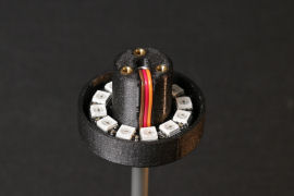
System electronics: a ring of LEDs and a Yocto-Color-V2
The electronics are very simple: we plan to use a Yocto-Color-V2 and a ring of 12 Neopixel LEDs. And we'll even take advantage of the Yocto-Color-V2's internal animation system so that the pole will automatically signal if the experiment has ended unexpectedly.
The mechanical part
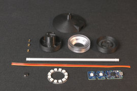
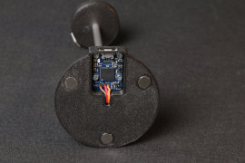
As we're going to be making several of these, we've opted for a simple design: a base containing the Yocto-Color-V2, an aluminum tube, and a head containing the LED ring. The head is in three parts, held together with screws and threaded inserts. The base is fitted with magnets, just in case we need a little extra stability. Nothing very original, apart from the optical part, which imitates the geometry of a prism to reflect outwards as much light as possible .

3D modeling, note the geometry of the transparent ring
The plastic parts are printed with an FDM printer, with the exception of the optical ring, which was printed with an SLS printer in transparent resin. Although a little translucent, the result is quite acceptable, even if the fact of having had to print the ring at an angle gives it somewhat strange optical properties from some angles. That said, it's likely that printing the ring with "transparent" filament would have worked too.

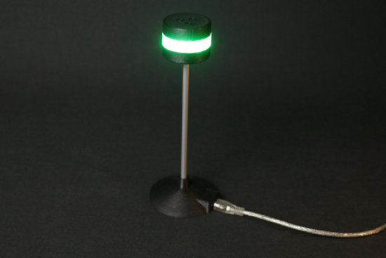
The same, in real life
The software part
We'd like our indicator to behave as follows:
- Blue on power-up, so we can see the experiment's power-cycle
- Green while the experiment is running
- Red if there was no news from the experiment for more than 5 seconds
- White when the experiment has finished without a hitch
You could also call it a luminous watchdog. This translates into an initialization code that does most of the work:
# make sure, Power-on color is blue
colorAtStartUp = 0x000080 #blue
startupcolor = ledcluster.get_rgbColorArrayAtPowerOn(0,12)
mustSetStartUpColor = False
for c in startupcolor :
if c!=colorAtStartUp : mustSetStartUpColor=True
if mustSetStartUpColor:
ledcluster.set_rgbColorAtPowerOn(0, 12, colorAtStartUp)
ledcluster.saveLedsConfigAtPowerOn()
# Create two animations
green = 0x008000
red = 0x400000
redhot = 0xFF0000
# animation #0 : steady green
ledcluster.resetBlinkSeq(0)
ledcluster.addRgbMoveToBlinkSeq(0, green, 0)
ledcluster.addRgbMoveToBlinkSeq(0, green, 5000)
ledcluster.addJumpToBlinkSeq(0,1)
# animation #1 : flashing red
ledcluster.resetBlinkSeq(1)
ledcluster.addRgbMoveToBlinkSeq(1, red, 0)
ledcluster.addRgbMoveToBlinkSeq(1, red, 2950)
ledcluster.addRgbMoveToBlinkSeq(1, redhot, 0)
ledcluster.addRgbMoveToBlinkSeq(1, redhot, 50)
# link leds to animation #0, and start both animations
ledcluster.linkLedToBlinkSeq(0,12,0,0)
ledcluster.startBlinkSeq(0)
ledcluster.startBlinkSeq(1)
This function first checks that the first 12 LEDs are blue on power-up, and if not, configures the module accordingly. It then builds a first animation that turns the LEDs green for 5 seconds and jumps to a second animation that flashes the LEDs red. The first 12 LEDs are assigned at the start of the first animation, then the animations are launched.
In practice, when this function is called, the LEDs turn green, and after 5 seconds they automatically start flashing red. This behavior is managed internally by the Yocto-Color-V2 and no longer depends on the control program once it has been launched.
We then need a function that prevents the LEDs from turning red when called. This is done by reassigning the LEDs at the start of the first sequence. After calling this function, you must wait 5 seconds again for the LEDs to turn red.
# remapping the LEDs to the start of animation #0
# and thus prevent them from jumping to animation #1
ledcluster.linkLedToBlinkSeq(0, 12, 0, 0)
As long as the resetWatchDog function is called at least every 5 seconds, the LEDs remain green; if this function is no longer called, because the program has crashed for example, the LEDs turn red.
If the program terminates correctly, the LEDs can be reset to a fixed color, thus disconnecting them from the animations.
# assign a steady color to the LED ,
# this will unlink them from the animations
ledcluster.set_rgbColor(0,12,0x404040)
The test program looks like this:
errmsg = YRefParam()
if YAPI.RegisterHub("usb", errmsg) != YAPI.SUCCESS:
sys.exit("Init error" + errmsg.value)
leds = YColorLedCluster.FirstColorLedCluster()
print("found %s"%leds.get_friendlyName())
if leds is None: exit("No LED Cluster found")
initWatchDog(leds)
for i in range (0,10):
print("doing arbitrary work...")
YAPI.Sleep(1000,errmsg)
resetWatchDog(leds)
jobDone(leds)
YAPI.FreeAPI()
print("Done.")
If you run this program, the LEDs will turn green, and when the program is finished, the LEDs will turn white. By contrast, if you interrupt the program in the middle, the LEDs will turn red after 5 seconds.
Conclusion
The logic that controls the Yocto-Color-V2's LEDs makes it possible to produce some pretty interesting automations at low cost. Note that you'll find the same logic in other modules capable of controlling Neopixel LEDs, such as the Yocto-MaxiBuzzer, the Yocto-MaxiKnob, or the Yocto-RFID-15693.
As for our little experiment, we've placed it at the top of a shelf, where we can see it from a distance, while it remains accessible.

The first node of our little test bench is already at work
Now that it's working, it's time to build the others...

Let's get to work!

