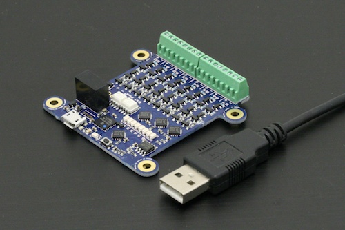
![]() Until now, we did not have much to offer to interface a PC with an external system using digital I/O lines. This gap is now filled by the new Yocto-Maxi-IO, that we will present today. Unlike a simple GPIO, the Yocto-Maxi-IO is an isolated interface, that can be used to safely connect without additional electronics up to 8 bidirectional digital lines, at the voltage of your choice.
Until now, we did not have much to offer to interface a PC with an external system using digital I/O lines. This gap is now filled by the new Yocto-Maxi-IO, that we will present today. Unlike a simple GPIO, the Yocto-Maxi-IO is an isolated interface, that can be used to safely connect without additional electronics up to 8 bidirectional digital lines, at the voltage of your choice.
The Yocto-Maxi-IO has been designed as a versatile product, that can fit many different use-cases. Each digital line can be configured dynamically as:
- A simple digital input, whose value is 0 or 1 depending on whether the absolute voltage applied to the connector is below or above 2 V. In opposition to GPIO ports found on development boards, that are usually limited to 3.3V, the Yocto-Maxi-IO can be used with voltages up to 25V, which makes it possible to read directly from a device using 5V CMOS or TTL standard, or even a 24V signal from an electric panel. Every input line has its own indicator Led showing the current logical level.
- A digital input with pull-up, driven by a device with open-collector output (or open drain). One can of course connect any kind of switch or transistor-output sensor to such kind of input. The input logic can be flipped internally if required.
- A simple digital output, to drive CMOS or TTL devices. Again, contrarily to typical GPIO ports, the voltage for the output high level can be configured as 3V or 5V (derived from the USB bus), or any arbitrary voltage (up to 25V) provided on a separate connector. The only limitation is that the high-level voltage must be the same for all output lines. The output impedance is 180Ω, which is enough to provide a few milliamps to drive a Led for instance.
- A digital open-drain output, 25V-tolerant as well.
The 8 input/ouputs can be read and written simultaneously as a single byte, or accessed one by one using atomic commands.

The Yocto-Maxi-IO
Example: driving a large 7-segment display
There are a number of useful applications for this device, specific to a particular device to be interfaced using a few digital lines. As an example, we have chosen something more generic, which looks very simple at first sight, but which would actually be significantly more complex to do without a Yocto-Maxi-IO.
The goal is to drive a large 7-segment display, as you can find them sometime to direct customers waiting in a line to a specific desk. Just for fun, we will make this a software sizing machine random generator, driven in Java: the user press on a big button, and the number will change continuously until it finally stops on a more-or-less random number.

The example of the day
At first sight, this is very simple: one input for the button, 7 outputs for the display segments. Except that if you look at it a bit closer, you will discover that a Led display of this size cannot be driven using a simple GPIO: as it is made of many Leds connected in serial, you need a voltage between 18 to 25V to light it, which would require a transistor-based electronic board to drive it from a GPIO, with potential ground path issues if the voltage source is not in common ground with the PC.
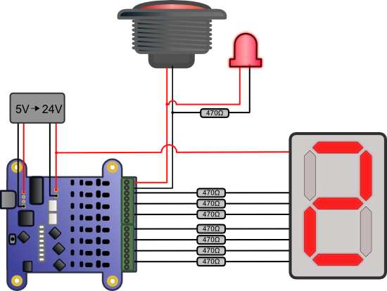
Fortunately, all of that is handled transparently by the Yocto-Maxi-IO. We will simply reuse a tiny 5V to +/-12V DC/DC converter from on old prototype to create a "24V" source from the USB bus, and provide it to the Yocto-Maxi-IO as external voltage source to drive outputs. As our 7-segment display works in common anode mode, the 24V source is applied on the display anode, and the Yocto-Maxi-IO will pull each Led cathode to 0V to light them up (inverted output).
The input for the button is implemented using a pull-up input (aka open collector). As our big button features a built-in 12V Led we connect it in parallel to the switch so that the pull-up (driven from software as well) lights up the button at the same time. Here is the final connection scheme (we have added some resistors on the electric wires to limit current, just to be safe):

The connection scheme
Software
The software sets up the Yocto-Maxi-IO as described above (bit 0 is allocated to the button, bits 1-7 to the display), waits for a button press and rolls the dice. The digit-to-segments conversion is done simply using a table. We have taken the sample program Doc-GettingStarted-Yocto-Maxi-IO from the Yoctopuce library as starting point, and replaced the main code by this one:
int sevenSeg[] = {
0xde,0x88,0xe6,0xea,0xb8,0x7a,0x7e,0xc8,0xff,0xfa
};
// enable external power source
io.set_outputVoltage(YDigitalIO.OUTPUTVOLTAGE_EXT_V);
// configure bit 0 as input, bits 1..7 as regular output
io.set_portDirection(0xFE);
// reverse polarity for all bits
io.set_portPolarity(0xff);
// repeat until disconnected
while(io.isOnline()) {
// turn on button, wait for press
io.set_portOpenDrain(0x01);
do {
YAPI.Sleep(10);
} while(io.get_bitState(0) == 0);
io.set_portOpenDrain(0x00);
// roll the dice for a random duration
double frameDuration = 3.0; // [ms]
do {
digit = (digit+1) % 10;
frameDuration *= 1.1+Math.random()/10;
io.set_portState(sevenSeg[digit]);
YAPI.Sleep((int)frameDuration);
} while(frameDuration < 800);
// flash the number 5 times
for(int i = 0; i < 6; i++) {
io.set_portState(0);
YAPI.Sleep(100);
io.set_portState(sevenSeg[digit]);
YAPI.Sleep(100);
}
}
The result
Here is the result:


