![]() At Yoctopuce, we like to buy random sensors, just to check if we can make them work with Yoctopuce hardware. This week we chose the GY-US42V2 sold by Play-Zone.ch and referenced as a "SRF02".
At Yoctopuce, we like to buy random sensors, just to check if we can make them work with Yoctopuce hardware. This week we chose the GY-US42V2 sold by Play-Zone.ch and referenced as a "SRF02".
The theory of operation for this kind of sensor is quite straightforward. The device sends a sonic pulse that will bounce back on any obstacle and the sensor clocks the echo. This GY-US42V2 can measure distance form 20cm to 7.2M. This model is interesting because it uses the same transducer for emission and reception. This makes it very compact: it is approximately 22mm wide.
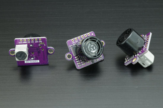
This is a GY-US12V2, not a SRF02
After receiving our sensor, we had a rather unpleasant surprise: there is no official documentation for it: no data-sheet, no application notes, nothing. After some detective work, we discovered that the GY-US42V2 and the SRF02 are definitely not the same device. There are almost compatible, but there are some differences at both hardware and software level. Despite this lack of documentation the GY-US12V2 can be found almost anywhere. We suspect this popularity comes from is compatibility with the Pixhawk flight controller. Anyway, after gathering small pieces of information from all over Internet and examined code written for both the GY-US12V2 and the SRF02, we managed to write a basic tutorial about using the GY-US12V2. This sensor can work in three modes: I2C, serial port and PWM output. Guess what? we do have devices designed to work with theses.
I2C
The default mode is I2C even though PCB markings might let you think otherwise. To make the GY-US42V2 work with a Yocto-I2C, you need to connect:
- Vcc to I2C power. Note that sensor can work with both 3.3v and 5V power supply.
- CR to SCL
- DR to SDI
- Both GND together

Connections between the GY-US42V2 and the Yocto-I2C
The default I2C address is 0x70. This mean that I2C write operations will always start with 2*0x70 = 0xE0 and read operation will start with 2*0x70+1 = 0xE1. To start a measure , with a result in centimeters, one has to send the 0x51 command. The measure total duration might vary, but the maximum is 65ms. To read the result, one needs to read two bytes from the sensor which are actually a big endian encoded word. It is therefore quite easy to write a basic job for the Yocto-I2C to make it start the measure, read the result and publish it as a Yoctopuce sensor.
writeLine {S}E051{P} expect 70:{A}{A} wait 70 writeLine {S}E1xx{A}xx{N}{P} expect 71:{A}($1:WORD)
On the SRF02 the I2C address can be modified, but the sequence for doing so doesn't work with the GY-US42V2. This means one cannot use several GY-US42V2 on the same I2C bus. Too bad.
Serial Port
Under the GY-US12V2 PCB, one can see three aligned rectangular pads with two of them labeled H and L. To make the sensor work in serial mode, you must bridge the central one with the one marked H.
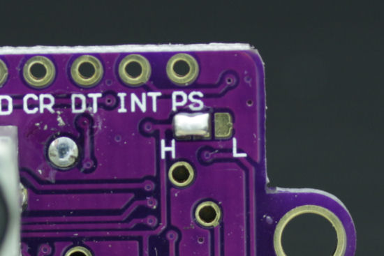
Configuring the GY-US12V2 in serial mode
To make the GY-US12V2 work with a Yocto-Serial you have to link:
- Vcc to Pwr
- CR to TD
- DT to RX
- Both GND together

How to connect the GY-US12V2 to the Yocto-Serial
In serial mode the default behavior is quite simple: the sensor makes continuous measurements at ~10Hz and sends the result as a 7 bytes frame looking like this:
5A 5A 45 02 XX YY CS
The distance is encoded in the XX and YY bytes. The seventh byte CS is a checksum computed as the LSB of 6 first bytes sum.
So, to use GY-US12V2 in serial mode with a Yocto-Serial, one has to configure the Yocto-Serial with "Frame-based binary protocol", 9600, 8N1.
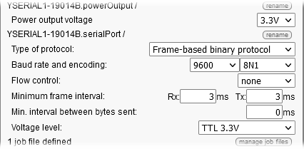
Yocto-Serial configuration
and once we have checked that we indeed receive the data frames, it is dead easy to write a job that will parse the data and present them as Yoctopuce sensors data. This job is just a reactive task containing only one line used to parse each sensor data frame.
expect 5A5A4502($1:WORD)(BYTE)
PWM
To make the GY-US12V2 run in PWM mode, one has to bridge the central pad and the one labeled L. In this mode the sensor will report result with electrical pulses. The length of each pulse will be proportional to the measured distance.
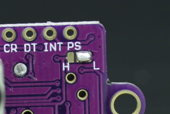
GY-US12V2 configured in PWM mode
The Yocto-PWM-Rx does not have any explicit power supply output, but you can steal 5V for the USB bus: just use the pads located next to the USB connector, but don't forget to tie ground from the sensor, the PWM input and USB. Since the Yocto-PWM-Rx is an isolated device, this is important. the PWM signal can be found on the DT pin.

Connection GY-US12V2 en mode PWM
As soon a the sensor is powered the PWM signal can be seen on the DT pin. However the result we get from the Yocto-PWM-Rx is somewhat disappointing: there is a lot of noise. A simple check with an oscilloscope can show us why: the signal found on the DT pin is not always a proper PWM signal, this prevents the Yocto-PWM-Rx from recognizing it.
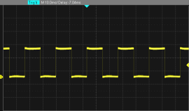
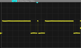
The PWM signal coming out of the GY-US12V2 can be a little bit strange.
But there is a work-around because the Yocto-PWM-Rx sees the bad PWM as pulses too long to be realistic. The pulses duration seem to be calibrated at 3ms per meter. So correct pulse duration should be in the 1.2ms ...21ms range for 20..700cm. If we configure this in the generic sensor matching PWM input, we will get a result directly in centimeter but invalid pulses will also be ignored. This makes the PWM mode almost useful.
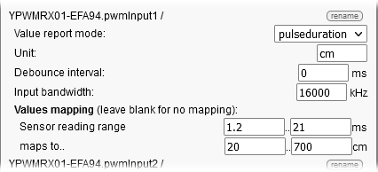
Generic sensor configuration
Conclusion
At the end of the day, using GY-US12V2 sensor with a Yocto-I2C, a Yocto-Serial or even Yocto-PWM-Rx is relatively easy once we have enough information about its interface inner working. Both I2C and serial mode seem to work quite well, but we do not recommend the PWM mode.
As a conclusion, note that ultra-sonic ranger finder technology has some serious limitation you should be aware of: precision is altered by both temperature and atmospheric pressure. Also, since sonic waves propagation is quite slow, if your sensor is mounted on a moving vehicle, you might end up in a situation where the sensor has moved, or rotated, too fast for it to see the echo from the last pulse. This would lead your system to believe the path is clear, although there is big obstacle right in front of it.


