![]() When you perform endurance tests with electronic circuits, you sometimes need to simulate a large current consumption. At first sight, this seems rather trivial, but don't get it wrong: there are a few hidden pitfalls which are only waiting for you to make a mistake in order to sabotage your experiment. This week, we show you how we built a small box with a consumption that we can drive by USB.
When you perform endurance tests with electronic circuits, you sometimes need to simulate a large current consumption. At first sight, this seems rather trivial, but don't get it wrong: there are a few hidden pitfalls which are only waiting for you to make a mistake in order to sabotage your experiment. This week, we show you how we built a small box with a consumption that we can drive by USB.
The key idea
The key idea is relatively trivial: to use small 12V halogen bulbs that we drive with a Yocto-MaxiPowerRelay. We found two types of bulbs, 21W and 32W. Powered in 12V, they consume about 3A and 2A. We used 4 of each type. We also used two large huge resistances of 10 and 22Ω which consume about 1A and 0.5A, still with 12 volts.

Our basic consumers
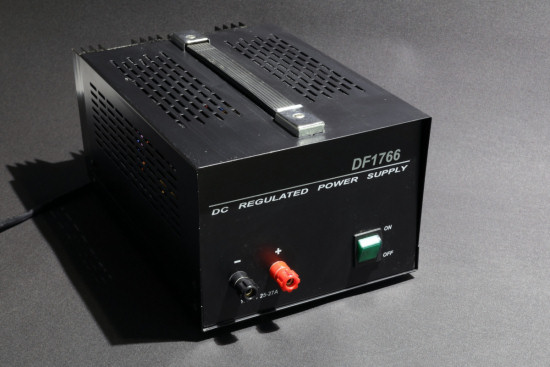
With 8 bulbs and our two resistances, we are potentially able to consume up to ~21.5A, by 0.5A increments. And it just so happens that we have a 25A power supply lying around.
Plan for a powerful power supply
Architecture
The heart of the system is therefore made of two Yocto-MaxiPowerRelays which can turn on our eight bulbs and our two resistances. For the system to remain easy to use, the Yocto-MaxiPowerRelays are connected to a Micro-USB-Hub-V2. We also added a Yocto-Thermocouple to monitor the temperature, as when one works with large currents, one is often very interested by the temperature.
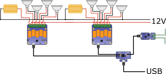
The heart of the system
The issues
You could think that everything needs only to be connected, and presto! the cat is in the bag. Except that there are a few issues that need solving before you obtain something not only usable but also reasonably reliable.
Heat
You know the tune: "nothing is lost, nothing is created, everything is transformed". We are trying to build an electrical device able to consume up to 250W. Inside the said device, this electrical energy is transformed. It is transformed into light, of course, but mainly into heat, a lot of heat. If you are unlucky enough to have ever touched a lighted halogen bulb, you know that well. So we must dissipate this heat, preferably while avoiding setting the house on fire. Therefore we decided to mount the bulbs into a metallic enclosure which helps to dissipate the heat. We also added a small 5V fan to extract the heat which is bound to accumulate in the enclosure. This fan is powered on the USB bus.
Note that mounting everything into a box brings a great advantage: you can easily move the system and it is easy to store.
The USB consumption
The Yocto-MaxiPowerRelay is an incredible product, but you must know that it can consume up to about 210mA when its 5 relays are active. A short review of USB consumption is in order:
- 2 Yocto-MaxiPowerRelay: 420 mA
- 1 Yocto-Thermocouple: 25 mA
- 1 Micro-USB-Hub-V2: 90 mA
- 1 small fan: 90 mA
The system can therefore potentially draw more than 600mA on the USB bus. It's a lot, the official limit is 500mA. Therefore, we decided to power the Micro-USB-Hub. To do so, we draw a little bit of current on the bulb power supply and we convert it into 5V thanks to a Pololu DC/DC converter. This tiny circuit accepts any voltage between 5.3 and 36V, and outputs up to 2.5A@5V. This ensures a more than comfortable margin.
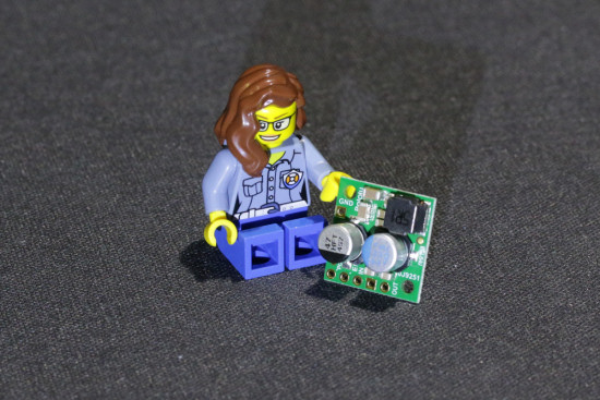
Pololu #2858: converts anything from 5.3V to 36V into 5V, up to 2.5A
Switching strong currents
Switching strong currents often has unexpected side effects. We noticed that each time we switched on a bulb, the voltage at the terminal of our power supply decreased down to 3 volts during about twenty ms. It's imperceptible to the naked eye, but the electronics notices it very well: we had more or less random UBS disconnections when switching on bulbs. We solved the issue by adding a diode and a huge 4700uF condenser between the power supply and the Pololu converter.
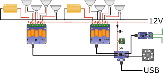
The complete diagram of the system
The box
So we managed to fit everything into a 27x18x7cm aluminium box. The wiring is rather consequent. We used electrical wires with silicon insulation so that it better resists heat and we made sure that no wire could touch the glass of the bulbs. The two resistances are screwed at the back of the box.
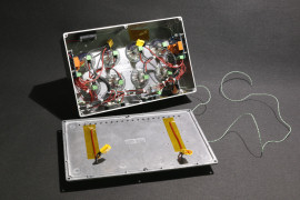
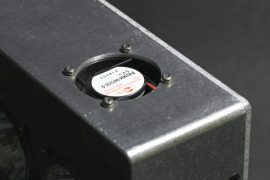
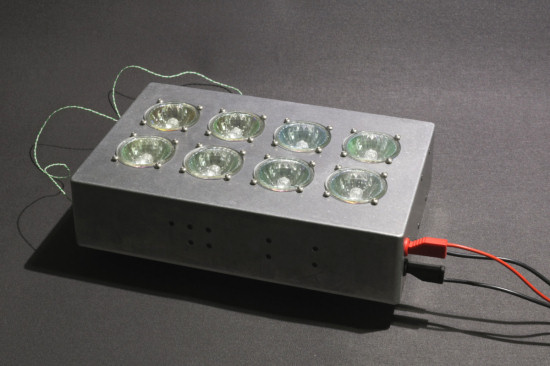
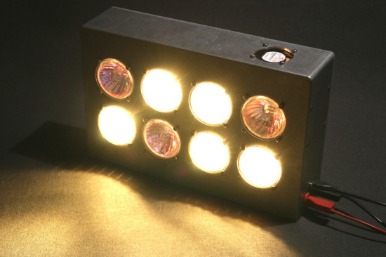


The box, when completed
What is it for?
You may wonder what's the use of this box, on top of wasting hard-earned energy. Well, you can use this device to check the behavior of a Yocto-Watt depending on the quantity of current going through it.
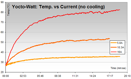
Temperature of a Yocto-Watt depending on the current going through it
Finally, note that this type of DIY allows us to automate tests which are always somewhat fastidious. But given the powers used and the produced heat, we discourage you from letting this type of experiment run without supervision.


