 Nowadays, most laboratory measuring tools have an RS232 port and/or a USB port, enabling you to drive them remotely. Usually, the manufacturers of this kind of instruments offer a proprietary software to drive them from a computer. This piece of software is usually more or less easy to use and not necessarily free. Obviously, it is tempting to get rid of the original software and to drive the devices on one's own. The question that we pondered this week was to know whether there was a universal way to drive this kind of equipment from an arbitrary software.
You have rightly guessed that if the answer was negative, we wouldn't have written a post about it. The answer is called SCPI (pronounced "skippy") for Standard Commands for Programmable Instruments. It's a very simple protocol, based on character lines. Most recent devices are SCPI compatible. The aim for this week is not to give you a SCPI crash course, but to show you that by relying on this protocol and a few Yoctopuce modules, you can drive an experiment automatically.
SCPI
The basic syntax of SCPI is extremely simple. Each command is a string of keywords separated by colons. Each keyword describes a precise context. Thus, on a SCPI compatible multimeter, to switch to voltmeter mode, you write:
:FUNCtion:VOLTage:DC
A command that elicits an answer ends with a question mark, in the same way as a question. For example, to know the DC voltage at the terminal of a voltmeter, you write:
:MEASure:VOLTage:DC?
And the voltmeter sends the answer in the shape of a floating point number written in scientific notation.
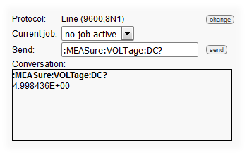
SCPI: a relatively simple syntax
Note that only the capital letters are necessary; you could also write the command as:
:MEAS:VOLT:DC?
Practical use
Let's see how to use SCPI to drive a very simple experiment: observing the behavior of a Zener diode depending on the voltage on its terminals. To do so, we need:
- A laboratory power supply, we used an AMEG HMP2020
- A digital voltmeter, we used a RIGOL DM3058E
- Two Yocto-RS232
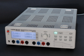
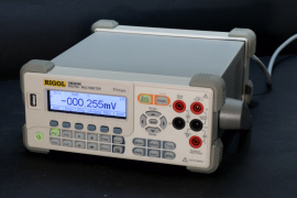
The two lab equipment used in the experiment
Kill-joys will certainly remark that these two devices have each a USB port on top of their RS232 port and will probably say that it is therefore dumb to buy two additional RS232/USB adapters. In fact, not really: to make the USB port of your laboratory device work, you need a specific driver, compatible with your operating system. Supposing that you manage to install this driver without trouble, nothing guarantees that it provides you with something usable, such as a virtual COM port. We don't want to speak ill, but during our tests, the RIGOL driver didn't want to install and the AMEG COM port was so virtual that we didn't find it, despite the successful driver installation.
To make a long story short, after a few unsuccessful trials, using a Yocto-RS232 makes a lot more sense: as all Yoctopuce products, it doesn't require any driver. You connect a Yocto-RS232 to each device and it works.
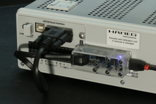
Use a Yocto-RS232 and you won't have to install any driver
Each of the Yocto-RS232 provides in the Yoctopuce API a SerialPort function to which you can assign distinct names thanks to the VirtualHub. To tell them apart easily, we used:
- AMEGHMP2020 for the power supply
- RIGOLDM3058 for the multimeter
When you have performed these preparatory tasks, you still have to code the course of the experiment: you must drive the power supply to run a current through a Zener diode and a resistance connected in series, then measure the voltage at the terminals of the diode, depending on the voltage to which the system is subjected.

The diagram of the experiment
To code everything, we selected the Python language, because it is very handy to program something fast on the back of an envelope. However, any other programming language would have done as well.
The code
The code is relatively short. The initialization part consists in finding the SerialPort function linked to the two devices.
if YAPI.RegisterHub("usb", errmsg) != YAPI.SUCCESS:
sys.exit("init error" + errmsg.value)
multimeter = YSerialPort.FindSerialPort("RIGOLDM3058")
if not(multimeter.isOnline()):
sys.exit("RIGOL DM3058 not connected")
powerSupply = YSerialPort.FindSerialPort("AMEGHMP2020")
if not(powerSupply.isOnline()):
sys.exit("AMEG HMP2020 not connected")
The code controlling the power supply is trivial, we write a function which powers on and off the output of the device, and a function used to set the output voltage. We take this opportunity to note that the syntax used by this device is a variant of the standard SCPI.
if state:
port.writeLine("INST OUT1")
port.writeLine("OUTP ON")
else:
port.writeLine("OUTP OFF")
def setVoltage(port,value):
port.writeLine("VOLT %1.3f"%value)
To read the voltage measured by the multimeter, we could simply send a read command and parse the result. But we'd rather use one of the Yocto-RS232 subtleties. It can automatically query a device and present the result in the form of a Yoctopuce sensor. We even wrote a function which configures this mechanism without having to go through the VirtualHub interface:
jobname = "voltmeter.job"
jobdata = '{"task1":{"interval":100,"script":[{"writeLine":":MEASure:VOLTage:DC?"},{"expect":"($1:FLOAT)"}]}}'
serial = port.get_module().get_serialNumber()
sensor = YGenericSensor.FindGenericSensor(serial+'.genericSensor1')
sensor.set_unit('V')
sensor.set_resolution(0.001)
port.uploadJob(jobname,jobdata)
port.writeLine(":FUNCtion:VOLTage:DC")
port.writeLine(":RATE:VOLTage:DC fast")
port.writeLine(":MEASure AUTO");
port.selectJob(jobname)
return sensor
This function creates on the module a job which queries the multimeter every 100ms and puts the result in the genericSensor1 function represented here by the sensor object. This function also configures the multimeter in voltmeter mode with the SCPI commands before running the job.
The code driving the experiment consists simply in increment the voltage in the experiment, waiting a little to make sure everything is stable, reading the voltage measured by the multimeter, and then starting again.
V = startVoltage
setVoltage(powerSupply,V)
setOutput(powerSupply,True)
print("V;A")
while V<=endVoltage:
YAPI.Sleep(250)
A = voltmeter.get_currentValue()
print(str(V)+";"+str(A))
V = V + voltageInc
setVoltage(powerSupply,V)
setOutput(powerSupply,False)
voltmeter = configureVoltmeterJob(multimeter)
runExperiment(powerSupply,voltmeter,1,10,0.1)
We plotted the result as a graph in Excel: the Zener diode that we used caps the voltage at ~6.4V: below this threshold the voltage at these terminals is the same as that of the power supply. Above this threshold, it stays at 6.4V, which is the principle of a Zener diode.
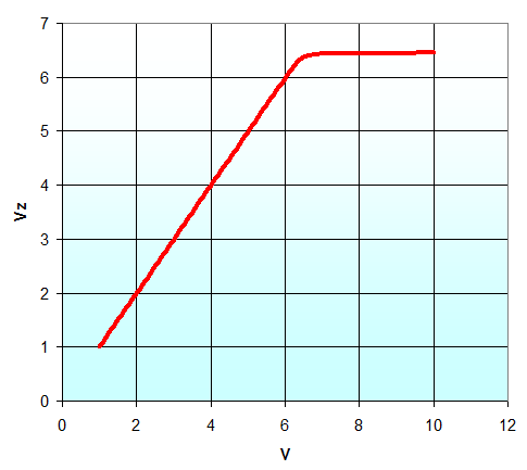
The result: the voltage is caped at 6.4V at the terminals of the Zener diode
Conclusion
With two Yocto-RS232 modules and some SCPI commands, we managed to set an automatic experiment up, admittedly trivial, but which would have been tedious had we had to collect the results by hand. In short, if you are tired of manipulating the buttons of your lab devices all day long, we have a solution :-)


