![]() Yoctopuce support has recently received several emails from distinct customers asking our opinion on the best way to interface a water meter with Yoctopuce devices. This week, we take the opportunity to explain all this in details. Follow the guide...
Yoctopuce support has recently received several emails from distinct customers asking our opinion on the best way to interface a water meter with Yoctopuce devices. This week, we take the opportunity to explain all this in details. Follow the guide...
How a water meter works
Almost all water meters designed for domestic use work in the same way: when water goes through the counter, it drives a small turbine, which in turn drives the gears of the meter. Some of these meters are also able to generate a pulse each time a given water amount has gone through.
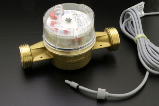
A pulse water meter and the reed switch sold with it
These pulses are generated with a small magnet embedded in one of the gears, rotating close to a reed switch. Each time the magnet nears the switch, the latter closes. It opens again as soon as the magnet moves away.
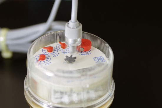
The reed switch is plugged in, one can see the magnet embedded in the deciliter gear, which does one turn per liter
We can therefore measure the quantity of water that goes through the meter by counting these pulses.
Interfacing
The best way to count the pulses is probably to use a Yocto-PWM-Rx. We only have to connect the reed switch directly on the module input, while remembering to use the built-in pull-up of the Yocto-PWM-Rx. Indeed, the reed switch only closes a contact while the pulse input of the Yocto-PWM-Rx is designed to detect voltage variations. The role of the pull-up is to draw the loop voltage to 3.3V through the resistance in the Yocto-PWM-Rx.

Connecting a reed switch to the Yocto-PWM-Rx
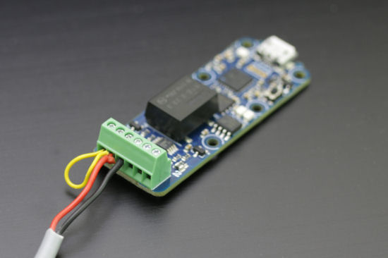
The same, in real life
When the switch closes, the input is directly connected to the ground and the voltage then drops to zero. When the switch opens again, the voltage goes back to 3.3V.
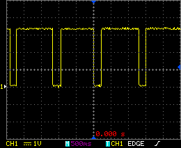
Signals generated by the reed switch thanks to the pull-up
About electro-mechanical contacts
Reed switches are electro-mechanical contacts, and like any mechanical switch, they have a strong tendency to bounce when they close. If we look at these pulses from very close with an oscilloscope, we can easily observe these rebounds.

Note that electro-mechanical switches bounce when they close
It so happens that the Yocto-PWM-Rx is fast enough to detect these rebounds and to count them as additional pulses. Fortunately, it has an debouncing function which allows the module to ignore all the pulses following the first one detected, over a certain duration. 25ms is a typical debouncing delay value.
Mapping pulses ⇨ total volume
In order to compute the water volume that goes through the meter, we can configure the Yocto-PWM-Rx so that its main value is the pulse counter. With the latest firmware (32442), you can even make it use a linear mapping to change the unit and you can even define your own unit.
For example, knowing that our meter generates one pulse per liter, if we want the Yocto-PWM-Rx to provide values in cubic meters, we only have to:
- Set the sensor in pulse counter mode (pulsecount)
- Define the value mapping as [0..2000000]⇨[0..2000]
- Define the unit as "m3"
- Without forgetting to configure debouncing at 25ms
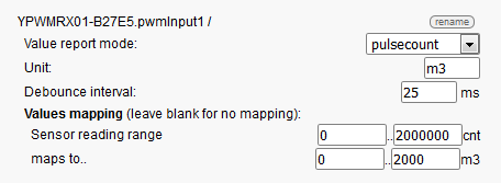
Configuration in 'm3 meter' mode
Note that the Yocto-PWM-Rx counters are set back to zero each time the module starts. It is therefore important that the application which drives the Yocto-PWM-Rx retrieves the counter values on a regular basis.
Mapping pulses ⇨ flow rate
As another example, let's imagine that we want to know the water quantity which goes through the meter over a given time in m³/hour. Knowing that in the case of our meter, a 1Hz signal = 1 l/s = 3.6 m³/h, we have to :
- Set the sensor in frequency mode
- Define the value mapping as [0..1000] ⇨[0..3600]
- Define the unit as "m3/h"
- Without forgetting to configure debouncing at 25ms
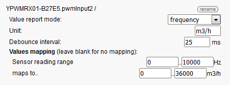
Configuration in m3/h mode
About mappings
Value mappings are performed by the Yocto-PWM-Rx thanks to the on-board calibration system, available on all the Yoctopuce sensors and described in the "Advanced programming" chapter of the documentation of each sensor. Therefore, it is essential that the beginning value interval covers all the possible values to be measured. But the two intervals also have to be included in the [-2×10ᵉ6..+2×10ᵉ6] range. You can use floating numbers, but only the first three decimals are taken into account.
One last piece of advice
The Yocto-PWM-Rx has two input channels. Nothing prevents you from using both to have, for example, a totalizer in m³ and a flow measurement in m³/h. To do so, you must connect both inputs to the same reed switch and configure both PwnInput functions of the module in the appropriate way. You don't need to connect the ground and the pull-up to the second input: both inputs share a common ground and one pull-up is enough. Adding a second one could even prove counter-productive.

Connecting a reed switch to both inputs of a Yocto-PWM-Rx
To conclude, here is a small video showing our working water meter, interfaced with a Yocto-PWM-Rx. The display is implemented with the Yocto-Visualization application.


