![]() Thanks to the new Yocto-I2C one can basically interface any I2C device, but one can also simply use it to test any I2C device. This week we decided to use this possibility to play with Amphenol's DLHR pressure sensors.
Thanks to the new Yocto-I2C one can basically interface any I2C device, but one can also simply use it to test any I2C device. This week we decided to use this possibility to play with Amphenol's DLHR pressure sensors.
Actually Yoctopuce's "R&D departement" has been lurking on theses for quite a while, wondering if they could make a good addition to our sensor line. Theses do pose a problem for us: they are available in more than a dozen pressure ranges. Making a device for every and each one of them is definitely not an option, hence our hesitation. Anyway, the Yocto-I2C is the perfect occasion to test this sensor and show you how to interface it.
The DLHR sensors line
Amphenol's DLHR sensors are differential sensors, they measure the pressure difference between their two inputs. They are available in several form factors and feature pressure ranges from 125 Pascals to 15 kPa. All of them feature at least an I2C interface. We chose to test a DLHR-L01D and a DLHR-L30G. They look like DIP packages so we soldered them a little bread board, this makes them much easier to wire.
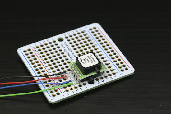
A DLHR-L01D differential pressure sensor, soldered on a breadboard
Connection
the first thing to do is downloading the sensor data-sheet. While reading it we learn that the sensor needs to be powered with 3.3V and pin 1,2,3 and 4 need to be connected to GND, Vsupply, SDA et SDL. No need for decoupling capacitor. So, basically, connecting a DLHR sensor to a Yocto-I2C is dead easy.

connection with the Yocto-I2C
Configuration
In the VirtualHub, the Yocto-I2C's configuration is also very simple, just set the I2C voltage level to 3.3V and the speed to 100kbps. The sensor is supposed to work at 400kbps as well, but we couldn't make it work at that speed.
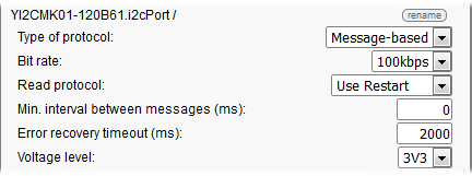
Configuration in the VirtualHub
Communication test
Once everything is connected and configured, it is time for the first communication test. The easiest way to test an I2C communication with a device is to check if the device can acknowledge its own I2C address. The sensor's data-sheet states that the DLHR address is 41 in decimal, that's 0x29 in hexadecimal. With the VirtualHub user interface we will send to the sensor:
- A start condition {S}
- The sensor address (7 bits) followed by the read bit set to 0, that's 0x29 * 2 + 0 = 0x52
- A stop condition {P}
If every works as it should, the sensor will acknowledge its address and the virtualhub user interface will show the answer as Address , column, answer, that is 29:{A}.
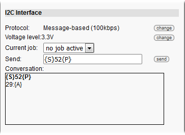
Test with the VirtualHub
.
If the answer shows a exclamation mark, that means that something went wrong, this could be a wiring problem, a bad address , bad speed setting etc.... Just fix the problem and power-cycle the device to make sure the sensor is in a known state.
Measures
A thorough study of the data-sheet shows that the DLRH's I2C protocol is much simpler than most other I2C sensors: there is no notion of registers. To start a measure one just has to write the 0xAA value on the IC port. To check if the measure is completed, one just has to read a byte from the sensor, if bit 5 is set to zero, then one can read 6 more bytes representing pressure and temperature encoded on 24 bit each. So:
- We write 0xAA at address 0x29*2=0x52 on the I2C port : {S}52AA{P}
- We read a byte : {S}53xx{N}{P}, note how 52 became 53 because of the read byte set to 1.
- The sensor will answer with his status byte. If bit 5 is set to zero, then we do a read operation again but with 7 bytes: status (1 byte) + pressure (3 bytes)+ temperature (3 bytes): {S}53xx{A}xx{A}xx{A}xx{A}xx{A}xx{A}xx{N}{P}. Note that all bytes are "ACKed" except for the last lone which is "NACKed" .
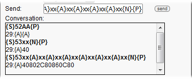
Interrogating the sensor
.
In the example above, the status byte is 0x40, the pressure value is 0x802C80 and the temperature value is 0x800C86. The only thing left to do is to convert theses values into meaningful units such as inches H2O and ░C, thank to the transfer functions available from the datasheet.

transfert fonction (extract from DLHR's datasheet)
.
Beware: theses functions are using constants which change depending of the chosen DLHR variant.
Automated measure
A this point, we could start to code the required I2C protocol with our favorite programming language. Turns out there is a better solution. Thank to its integrated job system the Yocto-I2C can query the sensor automatically show the result with its generic sensors functions. Here is a job example, made of 3 tasks. Nothing fancy, it is just a basic 3 states machine.
- Initialization task (periodic, once). Initialize a few variables. Beware: $OSDig et $FSS values are not the same for all DLHR variants, in this example we chose to work with a DLHR-L30G:
- assert !isset($state)
- compute $OSdig=0.1*2**24
- compute $FSS=30
- compute $state=0
- Measure task (periodc, 10hz) to start the measure
- assert $state==0
- writeLine {S}52AA{P}
- expect 29:{A}{A}
- compute $state=1
- Data retrieval task (periodic, 10hz): test the status byte, read the sensor values, convert data in ░C and inH2O and put the result in generic sensors 1 and 2.
- assert $state==1
- writeLine {S}53xx{N}{P}
- expect 29:{A}($s:BYTE).*
- assert ($s & 0x20) == 0
- writeLine {S}53xx{A}xx{A}xx{A}xx{A}xx{A}xx{A}xx{N}{P}
- expect 29:{A}($S:BYTE)($P2:BYTE)($P1:BYTE)($P0:BYTE)($T2:BYTE)($T1:BYTE)($T0:BYTE)
- compute $1 =-40 + ($T0 + ($T1<<8) + ($T2<<16))*125 / (2**24)
- compute $2=$FSS*1.25*($P0 + ($P1<<8) + ($P2<<16) - $OSdig ) /(2**24)
- compute $state=0
If you don't want to enter all this code manually, here is the matching job file, if you want to give it a try, just copy it on your Yocto-I2C file system. DLHR's Pressure data unit is water inches. So we leveraged the Generic sensors conversion system to convert theses in mm.
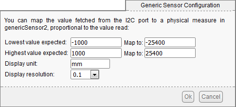
inches to mm conversion
Does it work?
To check if this works, we placed a vertical plexiglass tube inside a fish tank and connected the top of the tube to the DLHR with a fine tube. The water will try to raise in the tube, and thus create a slight over-pressure.
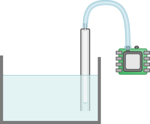
Experiment principle
The tricky thing was to find a tube fine enough: the DLHR inputs are very small. Then we started to pour water in the fish tank.
Tests: we used a fish tank
Since we used the Yocto-I2C's generic sensors, we can use the Yocto-Visualization to monitor the experience. Truth be told, we were very impressed by the sensor sensitivity, both can detect water level variations well below 1 mm. When one pours water in the fish tank, ripples are clearly visible on the graph.
we poured some water in the fish tank
On the other hand, we noticed some interesting phenomenons on the long term:
- Altough the DLHR is temperature compensated, quick temperature variations will significantly affect pressure measure.
- We noted a slow downward drift. We are not sure if this is caused by the sensor, evaporation or a tiny air leak in our tube
- Fun fact: this fish tank measurement system is very sensitive to vibrations, which, depending on the application, could be a good thing or not.
4 days measures
Conclusion
Yoctopuce sensors based on theses DLHR sensors are unlikely because there are too many variants. But with a Yocto-I2C, one can interface any of them and end up with something very similar to a regular Yoctopuce sensor.


