![]() A few years ago, we demonstrated how to use a Yocto-milliVolt-Rx to measure DC current, by measuring the very low voltage at the terminals of a shunt resistor. More recently, we thought that it could be useful to extend this scenario to the measure of strong alternative currents using simple ring-shaped current transformers, like current clamps.
A few years ago, we demonstrated how to use a Yocto-milliVolt-Rx to measure DC current, by measuring the very low voltage at the terminals of a shunt resistor. More recently, we thought that it could be useful to extend this scenario to the measure of strong alternative currents using simple ring-shaped current transformers, like current clamps.
Indeed, to measure strong currents, using a shunt is quickly restricted because the shunt heats up due to the current going through it. However, for alternative current, you can easily perform a measure by induction, with the help of the transformer principle:
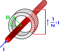
Measuring AC current with a transformer
(source: Biezl CC BY 3.0)
You can easily find this type of transformer in retail, even in the shape of a current clamp which can easily open and close around a wire. There are clamps with a specified output voltage - as the one on the left in picture below, specified to provide 0.1mV per amp in output, up to 30mV/300A - and others with a specified output current, as the one on the right, specified to provide 0.5mA per amp, up to 50mA/100A.


Two off-the-shelf current clamps
When the output is specified in current, you must imperatively connect to it a small resistance acting as a load, otherwise the current cannot flow. The load must be adapted to the specs of the secondary circuit so that the measure stays accurate on the whole range. Finally, you measure the voltage a the resistance terminals, which puts you back in the situation of a voltage output :-)
Measuring tiny AC voltage
You are therefore back to measuring a low voltage proportional to the current you must quantify, but this time it's an alternative voltage. For instance, here is the output of our current clamp for a resistive load of about 1A:

Output of our current clamp
One could consider using a Yocto-Volt to measure it, but it's not very accurate to measure very low voltages, in particular in AC mode. So we have decided to extend the firmware of the Yocto-milliVolt-Rx and of the Yocto-milliVolt-Rx-BNC so that they are able to measure AC voltages. If you install firmware 50047 or more recent on your module, you can find a new sampling option in the configuration panel:

AC sampling configuration
Note that AC sampling is based on an 600Hz oversampling and is designed to provide good results with 50Hz or 60Hz frequencies found on the mains. It won't work well on higher frequencies, nor on frequencies which are not a multiple of 10Hz. Nevertheless, for main frequencies, you should get a very decent accuracy. By configuring the voltage/primary correspondence of your amperometric transformer, the Yocto-milliVolt-Rx provides you with a direct read of the current flowing in the wire.
Selecting the measured conductors
When meausuring using a transformer ring, the result takes into account the current flowing in the all the wires going through the ring, also taking into account the direction of the current. Usually, you put there either the phase or the neutral, but not both because otherwise the fields cancel each other as the direction of the current in these two wires is opposed.
There is one interesting exception: by measuring simultaneously the phase and the neutral (but without the protective ground), you actually measure the system leakage currents (ground currents). If the value is non-null, it means that some current is escaping somewhere else. It's the principle used in differential circuit breakers to disconnect the circuit in case of electric shock.
A few pieces of advice
As a conclusion, here are a few pieces of advice if you want to use this solution.
 Warning: in opposition to the Yocto-Volt, Yocto-Amp, and Yocto-Watt, which are designed to provide a safety insulation, the Yocto-milliVolt-Rx provides only a functional insulation. Under no circumstances should it be connected directly to a hazardous live voltage, such as a shunt on the mains. For all the systems described in this post, the safety insulation comes from the current transformer, which provides the required reinforced insulation.
Induced parasitic currents: Take care not to bias your measure by running the current clamp output wires near another transformers or other cable radiating 50Hz emissions. Using a coaxial cable with the Yocto-milliVolt-Rx-BNC as shown below reduces the risk, and makes the connection simpler:

Our USB current clamp
Measuring power consumption: If your aim is to measure the power consumption, don't forget that with alternative current, the power doesn't always equal the product of the current and of the nominal voltage: if the load is inductive, you need a synchronous measure of the voltage and of the current to compute the power. In this case, you should rather use a true energy counter with an RS485 output for a higher quality measure.

