 Three years ago, we gave you a small preview of what could be a Yoctopuce module used to drive stepper motors. In the mean time, a lot of time has past, but this module is still not for sale. We do intend to offer it in the future, but if in between you need to drive a stepper motor for a simple application, we may have a solution for you ...
The aims that we set for ourselves in the design of a Yoctopuce module dedicated to driving stepper motors are rather ambitious: microstepping, synchronous multi-axes movements, controlled and predictable acceleration and torque curves, and so on. There are already on the market products that can do all of these, we weren't going to be less performing than others. Thus, it's taking us much longer than anticipated ...
However, there are some simple applications where these advanced features are not required and where one simply wishes to use a stepper motor for its capacity to precisely control the amplitude of a movement. The question is therefore to know what the strict minimum required to drive a stepper motor is and if an existing Yoctopuce module can fulfill this minimum.
How a stepper motor works
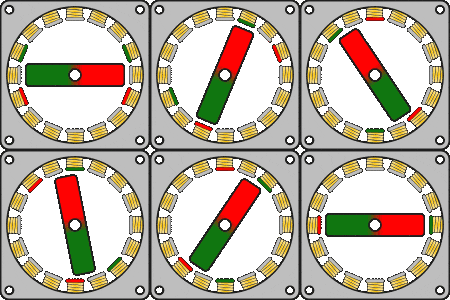
From an electric stand point, a stepper motor is in fact a set of electromagnets in the engine frame, and permanent magnets, solidary to the motor axis. Depending on the direction of the current going through the electromagnets, they attract or repulse the North pole, and the South pole reciprocally, of the permanent magnets. By selecting the electromagnets activation sequence, we can thus lead the motor into a desired position.

Theoretical principle of the driving of a stepper motor
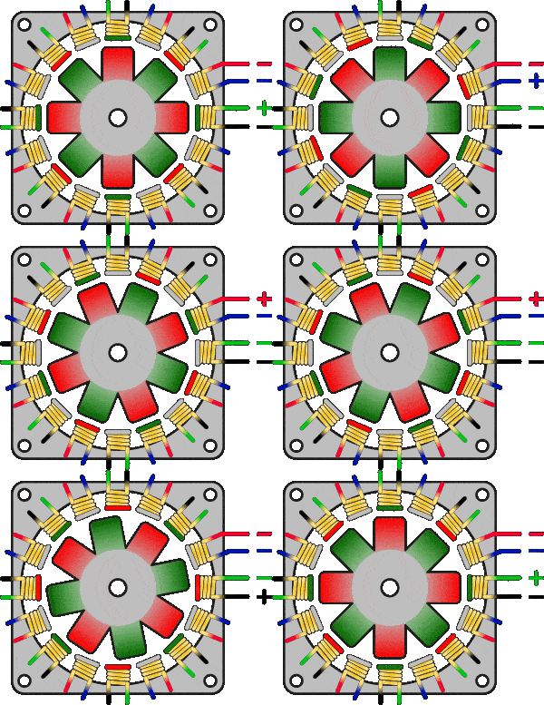
To avoid multiplying command wires, we make the motor axis symmetrical, which makes it possible to use the same conductors for several coils and obtain the same result:

Optimizing the coils in a stepper motor
Thus, four wires are enough to generate four distinct stable electric states in the motor, enabling us to reach, by an adequate activation sequence, sixteen distinct mechanical positions, called sixteen step. In real life, most motors multiply the coils and the magnets in the motor, in order to typically obtain 200 steps per motor revolution. But the working principle remains exactly the same and four wires are enough, whatever the number of steps. You can control the direction of rotation of the motor by flowing the current through these wires in the correct order, and you can determine the rotational speed by choosing the frequency of alternation.
Driving it with a Yoctopuce module
From an electric stand point, stepper motors typically use voltages from 3.2V to 24V, depending on the models. Actually, the voltage is not critical, it's the current that runs in the coils that is. But without a current limitation mechanism, the indicated maximum voltage allows you to limit the current through the internal resistance of the coils. Involved currents are typically of a few tens of mA to a few amps, depending on the size of the motor.
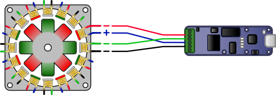
The Yoctopuce module which allows you the most easily to apply on four outputs voltages up to 28V for currents up to 250mA is the Yocto-IO. Each output is actively driven towards the power supply voltage or towards ground, enabling you to inverse the current direction between a pair of wires.
If you connect the wires in the correct order, you only need to activate the outputs one after the other in the increasing order to make the motor revolve in one direction, and in the reverse order to inverse the motor direction.

Thus, the following code is enough to bring the motor from the A position to the B position:
while(step != B) {
int coil = step & 3;
digitalio.set_portState(1 << coil);
step += (B > A ? +1 : -1);
YAPI.Sleep(5); // 5 ms delay between steps
}
Demonstration
On this principle, here is a short example written in HTML and JavaScript, where we drive a small Pololu #1208 stepper motor, directly from a web page to go from one position to another.
This example code is available on GitHub: it's only 75 lines long, half of it to manage the graphic interface.
Conclusion
We showed that a Yocto-IO can effectively be used produce controlled movements with a small stepper motor. In a real life application, we could use a Yocto-Maxi-IO-V2 instead to add inputs for limit switches.
If we needed more power, we could also use a Yocto-MaxiCoupler-V2 supporting 48V and 1.3A. But unlike the outputs of the Yocto-IO, an optocoupled output draws only in one direction. We would therefore need to use two channels per motor wire, one to draw towards the power supply, the other to draw to towards ground. Alternatively, instead of using a 4-wire bipolar stepper motor, one could use a 6-wire unipolar stepper motor, connect the two center-tap wires to the power supply and draw the four remaining wires to towards ground only.


