 This week, we're going to do a little DIY. The aim is to make a "smart" extension cord that measures consumption and can be controlled remotely using the WiFi network.
The aim of this DIY project is to create 5 extension cords that can be installed in different places in a house, so that we can establish more precisely which appliances are consuming what and when. This kind of information is very useful if you have solar panels and are trying to optimize your electricity consumption.
Regular readers will recall that we have already built such a device in a previous post. The version we're discussing today has more or less the same functionality, but is more compact and has just one output.

The socket
Required components
To build this "smart" extension cord, we used:
- A box with a socket, the ones we found are OBO T60.
- A Yocto-MaxiPowerRelay.
- A Yocto-Watt.
- One YoctoHub-Wireless-n.
- One Mini-Battery-Supervisor.
- Two 1.27-1.27-11 cables.
- A RAC04-C/W AC/DC 5V converter.
- An electric wire with a male plug with a bead.
- Some 3mm plexiglass and screws (Fix-3x8mm).
Note: Recom's AC/DC converter is no longer in production and is advertised as "Not recommended for new designs". In our case, this wasn't an issue, as we were making a single batch of 5 extension cords and we had enough RAC04-C/Ws in stock.
Wiring
There are two ways of wiring this plug. Either the socket electronics (YoctoHub-Wireless-n, Yocto-Watt, and so on) are part of the measure, or the socket measures only the consumption of the connected device. We have decided not to include the consumption of Yoctopuce modules in the measure.

Socket wiring
Construction
The first step is to assemble the Yoctopuce module stack. To do this, we start by soldering all the 1.27 connectors to the modules. That is, on the two slave ports of the YoctoHub-Wireless-n, as well as on the USB ports of the three Yoctopuce modules.

The 1.27 connectors soldered to the modules
Next, we solder the AC/DC output wires to the Mini-Battery-Supervisor power socket. And set the Mini-Battery-Supervisor 's microswitch for a cut-off voltage of 3.6V.

The correct configuration of the Mini-Battery-Supervisor
We then stack the YoctoHub-Wireless-n, Yocto-MaxiPowerRelay and Yocto-Watt using Fix-3x8mm. Remember to plug in the 1.27 cables and the WiFi antenna cable as you go, because when everything is assembled, access to the sockets is very complicated.
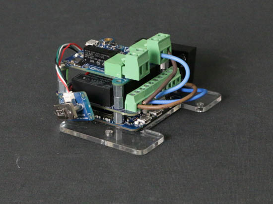

The Yoctopuce module stack
Before inserting the modules into the junction box, we drill three holes in the side of the box. The first is for the 220V cable, the second for the WiFi antenna. The last hole is for the Mini-Battery-Supervisor's USB port. The last hole is made with a Dremel, with variable results...

Three holes for 220V, USB, and antenna
We can now wire up our system as shown above.
Finally, all that's left to do is secure everything in the box. We fixed the stack of modules to a PVC plate which we laser-cut to size. If you don't have access to this type of tooling, you can use a FixPlate-X2 and/or drill holes in the bottom of the box to secure everything.
")
All that's left is to shoehorn everything in :-)
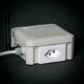
Result
Once the cover is closed, you have an extension cord that can be switched on and off remotely, and which is capable of measuring the power consumption of the connected device.

Here is our smart extension cord
Thanks to the USB port on the front, you can configure the WiFi network to which the YoctoHub-Wireless-n is to connect. The Yocto-MaxiPowerRelay and Yocto-Watt can then be used by all our libraries and our tools.
These extension cords will be used to understand a little better what the real consumption of specific appliances is, and at what time of the day. Using Home Assistant, we'll even be able to automate these outlets, but that's for a next post.

