 This week, we are going to do a small and amusing DIY: we will build a speedometer for a hamster wheel.
Principles
The technique to compute the wheel speed is very simple: you stick a magnet on the wheel and a "reed switch" on the wheel holder. If these two elements are correctly aligned, you can detect the passage of the magnet in front of the switch by measuring the resistance of the switch.

The reed switch enables you to detect the passage of the magnet at each turn
In simpler terms, the two wires of the reed switch are connected only when the magnet is opposite the reed switch. You can thus determine the speed by measuring the elapsed time between two contact closures.

The reed switch is mounted on the cage and the magnet is glued on the wheel
Detecting the passage of the magnet
We have two modules which you can use to detect the reed switch closure, the Yocto-Knob and the Yocto-PWM-Rx.
For this system, we decided to use the Yocto-PWM-Rx because it has a debouncing feature and it can automatically count the number of contact closures.
Reed switches have a tendency to rebound when they change state, which generates parasitic pulses. You can configure the Yocto-PWM-Rx to filter these rebounds. If we had selected to use a Yocto-Knob, we would have had to deal with the rebounds through coding in our software.
The Yocto-PWM-Rx can also automatically count the number of pulses, that is the open->closed->open transition. Again, it's something we would have had to manage through coding if we had used the Yocto-Knob.
Because the reed switch is a passive element, we must use the pull up of the Yocto-PWM-Rx to power the loop. This assembly in open drain mode is described in details in section 2.2 of the documentation, but here is the connection needed to use input 1:

The Yocto-PWM-Rx is connected in open drain mode
When you have performed the connection, you must configure the Yocto-PWM-Rx to activate the two features mentioned above. In our case, we must use a 5ms anti-rebound filter and the input must return the number of pulses.
- debouncePeriod : 5ms
- pwmReportMode : Pulse count (number or observed pulses since the last reset of the pulse counter)
You can do so with the VirtualHub or directly in the application code as we are going to see later.
Now that we know how to compute the number of turns done by the wheel, let's see what we can make of the information.
The counter
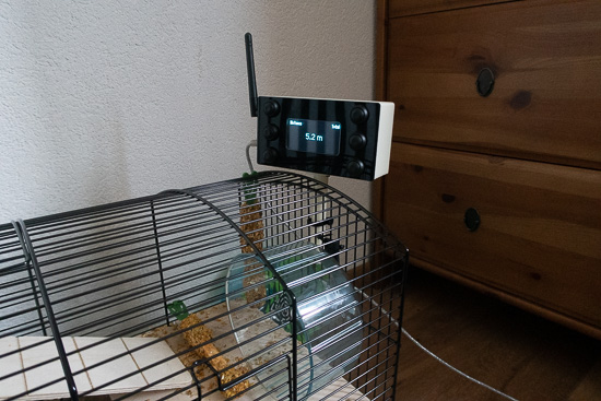
For this DIY, we decided to use a Yocto-PWM-Rx to count the wheel turns and a Yocto-MaxiDisplay to display the current value. We connected these two modules on a YoctoHub-Wireless-g and the application runs on a Raspberry Pi.

.
We chose to move away the Raspberry Pi and use a YoctoHub-Wireless-g because this enabled us to obtain a more compact installation. It's not quite the size of the Raspberry Pi which is an issue, but the USB cables which immediately make the installation more voluminous. Thanks to our various connectors and cables, it is possible to obtain a more compact installation.

The installation is quite compact
From a software standpoint, moving away the Raspberry Pi doesn't change anything, we must simply use the YoctoHub IP address instead of usb when initializing the API.
The application
We decided to write the application in C#, more specifically in C# .NET Core 2.1 because this environment is very easy to deploy on a Raspberry Pi or any other computer.
Note: As the application code is relatively long, we are going to detail only the part that computes the speed of the wheel.
Before using the YPwmInput, we make sure that the input is correctly configured.
{
pwmInput.set_debouncePeriod(5);
pwmInput.set_pwmReportMode(YPwmInput.PWMREPORTMODE_PWM_PULSECOUNT);
pwmInput.get_module().saveToFlash();
}
Then, we initialize our internal variables and we register a value callback which is automatically called as soon as the Yocto-PWM-Rx detects the passage of the magnet.
{
...
log("use PWM " + pwmInput.get_hardwareId());
configurePWMInput(pwmInput);
ResetRun(pwmInput.get_pulseCounter());
pwmInput.registerValueCallback(count_callback);
string errmsg = "";
while (true) {
YAPI.Sleep(1000, ref errmsg);
...
}
}
This callback function receives as argument the pulse count, that is the number of times the magnet was in front of the reed switch. We can then compute the wheel speed by computing the time between each call to the callback.
{
int count = Int32.Parse(value, CultureInfo.InvariantCulture);
if (count == _initialCount) {
return;
}
ulong now = YAPI.GetTickCount();
ulong deltaTime = now - _lastTickCount;
long deltaCount;
if (_lastCount > count) {
deltaCount = count + 999999 - _lastCount;
} else {
deltaCount = (count - _lastCount);
}
double speed = (double) deltaCount / deltaTime;
Debug.WriteLine(String.Format("count ={0} time={1} speed={2}",
count, deltaTime, speed));
//Update Max speed
if (_maxSpeedCMS < speed) {
_maxSpeedCMS = speed;
}
_totalCount += deltaCount;
_lastSpeedCMS = speed;
_lastTickCount = now;
_lastCount = count;
}
We must then convert this speed into km/h and display it on the screen.
{
return _lastSpeedCMS * _perimeterKm * 3600000;
}
The application can display a lot more of information than the current speed. It can, among other things, display the following information:
- the current speed
- the maximum speed
- the average speed
- the covered distance
- the duration
These pieces of information are available for the latest run of the hamster, or on a daily basis. You can also display these values in km/h or in mph. You can use the Yocto-MaxiDisplay buttons to select the displayed information.
Moreover, you can save each run of the hamster in a CSV file in order to perform stats at a later time.
As usual, the source code of the application is available on GitHub:
https://github.com/yoctopuce-examples/hamster_wheel
Running the application
We are going to skip the compilation and the application installation on the Raspberry Pi, as we already have a post dedicated to this topic. We are simply going to describe how to run the application when it is installed on the Raspberry Pi.
To work, this application requires some additional information which you can give on the command line.
The first one is the wheel diameter in millimeters. This parameter is compulsory and is passed with the --diameter option.
The second one is the address of the YoctoHub. By default, the application uses the modules which are connected on the USB ports, but if you move away the Raspberry Pi, like we did, you must specify the YoctoHub URL with the --url option.
Then, the application uses the input of the Yocto-PWM-Rx named wheel, but if you want to use a hardware ID or another logical name, you can specify it with the --pwmInput option. Note: if you are not clear about the notion of hardware ID or logical name, you can read our post on the logical structure of Yoctopuce devices.
In the same way, you can specify the hardware ID of the display and of the buttons if you are not satisfied with the default configuration.
In our case, we use a wheel with a 138mm diameter, the address of the YoctoHub is 192.168.2.49, and we want to save the statistics in a /home/pi/hamster_stat.csv file.
The command for the application is therefore the following:
HamsterWheel --diameter 138 --url 192.168.2.49 --export_csv /home/pi/hamster_stat.csv
We don't need to specify the hardware ID of the Yocto-PWM-Rx as we assigned the "wheel" logical name" to the input on which the reed switch is connected.
")
The hamster in the middle of a jogging session:-)
Conclusion
This idea has already been implemented by other DIYers, but they all used Arduinos. We wanted to show you that it was possible to build a similar system with Yoctopuce modules.
As you can see with our solution, the electronics is very simple, the difficulty consists in making a not too large enclosure which must be placed out of the rodent's reach.

