![]() Three weeks ago, we presented the new Yocto-MaxiKnob which enables you to quite easily interface control panels. This week, we show you how to embed alphanumeric displays in you control panel by using only one Yoctopuce module: the Yocto-I2C.
Three weeks ago, we presented the new Yocto-MaxiKnob which enables you to quite easily interface control panels. This week, we show you how to embed alphanumeric displays in you control panel by using only one Yoctopuce module: the Yocto-I2C.
The idea is to use displays based on the HT16K33 led driver manufactured by Holtek which can drive up to 128 leds. For this demo, we ordered ours from Adafruit, but any other model based on the same chip works in the same way, only the constants used to drive the leds may change.
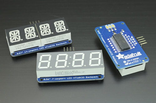
Adafruit displays based on the HT16K33
.
The HT16K33
A careful study of the HT16K33 datasheet shows that this chip is relatively easy to drive with I2C. Address registers are 4 bit long, and the configuration parameters are 4 bit long as well. In other words, each configuration command takes a single byte.
- Its I2C address varies between 0x70 and 0x77 depending on input S2, S1, and S0 configuration
- To initialize the chip, you must:
- Switch the clock on by writing 0x1 at address 0x2
- Configure the INT/ROW pin by writing 0x0 at address 0xA
- Switch the display on by writing 0x1 at address 0x8
- Configure the intensity at 50% by writing 0x8 at address 0xE
- To turn the leds on, you must write the starting offset (usually 0) at address 0 followed by the data bytes where each bit corresponds to one led. Maximum of 16 bytes total.
We can therefore easily write the beginnings of the Python class which instantiates itself with a YI2cPort function which enables us to initialize the HT16K33 chip and to send data to it:
i2cPort = None
def __init__(self,I2C_port,addr): # YI2cPort function and A2A1A0 (0..7)
self.addr= (0x70 | ( addr & 3)) <<1
self.addrStr= format (self.addr , '02x')
self.i2cPort=I2C_port
self.i2cPort.set_i2cMode("400kbps")
self.i2cPort.set_i2cVoltageLevel(YI2cPort.I2CVOLTAGELEVEL_3V3)
self.i2cPort.reset()
self.i2cPort.writeLine("{S}"+self.addrStr+"21{P}") # wake up
self.i2cPort.writeLine("{S}"+self.addrStr+"A0{P}") # INT/ROW config
self.i2cPort.writeLine("{S}"+self.addrStr+"81{P}") # Display ON
self.i2cPort.writeLine("{S}"+self.addrStr+"E8{P}") # Intensity = 50%
def sendData(self,rawdata):
cmd ='{S}'+format(self.addr, '02x')+"00";
for i in range(0,len(rawdata)) :
cmd=cmd+format(rawdata[i], '02x')
cmd+="{P}"
self.i2cPort.writeLine(cmd)
It's important to understand that the correspondence between each data bit and the leds depends on the way the display manufacturer has interconnected the leds and the HT16K33. However, even if the manufacturer "forgot" to document this correspondence, you can easily determine it empirically by testing each bit one after the other.
Adafruit 7-Segment LED Backpack
Adafruit sells a small HT16K33-based PCB, on which you can solder a 7-segment 4-digit display. Each digit corresponds to a byte located at an even address in the HT16K33 memory, the two center dots are treated as a distinct character, stored at address 0x04. For each digit, the bits are organized as follows:
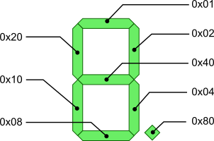
Organization of the Adafruit 7-Segment LED Matrix Backpack
For example, if you want to display a 1, you must send the byte 0x02 + 0x04 = 0x06; if you want to display a 2, you must send 0x01+0x02 +0x40 +0x10 + 0x08 = 0x5B; more generally, the list of the constants corresponding to digits 0 to 9 is 0x3F, 0x06, 0x5B, 0x4F, 0x66, 0x6D, 0x7D, 0x07, 0x7F, 0x6F. You can therefore code a small function which writes any integer between -999 and 9999 on the display:
digits = [0x3F, 0x06, 0x5B, 0x4F, 0x66, 0x6D, 0x7D, 0x07, 0x7F, 0x6F]
def showInteger(self, number):
number = round(number)
if number < -999: raise Exception("min value is -999")
if number > 9999: raise Exception("max value is 9999")
data = [0] * 10 #array of 10 zeros
number = str(number)
index = 8
for i in range(0, len(number)):
if number[-i - 1] == "-": # negative sign
data[index] = 64
else:
data[index] = self.digits[ord(number[-i - 1]) - 48];
index = index - 2
if index == 4: index = 2 # skip middle colon
self.sendData(data)
Adafruit 14-segment LED Backpack
Adafruit also sells a 14-segment version of its board. This time, each digit is driven by two consecutive bytes organized as follows:
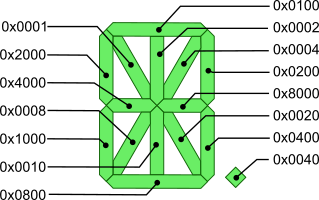
Organization of Adafruit 14-segment LED Alphanumeric Backpack
For example, if you want to display a capital M, you get 0x1000 + 0x2000 + 0x0001 + 0x0004 + 0x0200 + 0x0400 = 0x3605, so you must send the bytes 0x36 and 0x05.
From this, you can build a representation of all the ASCI characters between 32 and 127 and code a function which displays an arbitrary character string on the display. The only subtlety is to manage the decimal point which is not necessarily a full character on the display.
# representation for ASCII characters 32..127
font = [0x0000, 0x0006, 0x0220, 0x12CE, 0x12ED, 0x0C24, 0x235D, 0x0400,
0x2400, 0x0900, 0x3FC0, 0x12C0, 0x0800, 0x00C0, 0x0000, 0x0C00,
0x0C3F, 0x0006, 0x00DB, 0x008F, 0x00E6, 0x2069, 0x00FD, 0x0007,
0x00FF, 0x00EF, 0x1200, 0x0A00, 0x2400, 0x00C8, 0x0900, 0x1083,
0x02BB, 0x00F7, 0x128F, 0x0039, 0x120F, 0x00F9, 0x0071, 0x00BD,
0x00F6, 0x1200, 0x001E, 0x2470, 0x0038, 0x0536, 0x2136, 0x003F,
0x00F3, 0x203F, 0x20F3, 0x00ED, 0x1201, 0x003E, 0x0C30, 0x2836,
0x2D00, 0x1500, 0x0C09, 0x0039, 0x2100, 0x000F, 0x0C03, 0x0008,
0x0100, 0x1058, 0x2078, 0x00D8, 0x088E, 0x0858, 0x0071, 0x048E,
0x1070, 0x1000, 0x000E, 0x3600, 0x0030, 0x10D4, 0x1050, 0x00DC,
0x0170, 0x0486, 0x0050, 0x2088, 0x0078, 0x001C, 0x2004, 0x2814,
0x28C0, 0x200C, 0x0848, 0x0949, 0x1200, 0x2489, 0x0520, 0x3FFF]
def showString(self, string):
data = [0, 0, 0, 0, 0, 0, 0, 0]
n = 0
index = 0
while n < len(string):
if index >= 8:
raise Exception("String \"" + string + "\" cannot be displayed ")
code = ord(string[n])
if code < 32 or code > 127: raise \
Exception("Character \"" + string[n] + "\" at position #" + str(
n + 1) + " of string \"" + string + "\" cannot be displayed ");
digit = 0
if code == 46: digit = 0x4000 # decimal point
digit = digit | self.font[code - 32]
n = n + 1
if code != 46 and n < len(string) and string[n] == ".":
digit = digit | 0x4000
n = n + 1
data[index] = digit & 0xff
data[index + 1] = digit >> 8
index = index + 2
self.sendData(data)
Several displays as the same time
Now you know how to drive one of these displays with a Yocto-I2C, but you don't necessarily want to use one Yocto-I2C for each display. As the I2C is a BUS, and as you can more or less choose the I2C address of the HT16K33 by configuring the chip S0, S1, and S2 inputs, you can therefore connect several displays on the same Yocto-I2C, as long as you given them distinct addresses. On Adafruit products, you only need to bridge the A2, A1, and A0 contacts. The bridges set to 1 the corresponding bits of the I2C address of the HT16K33.
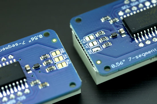
The address of the left one is 0x70, that of the right one is 0x71
You can therefore connect up to 8 HT16K33 on the same I2C BUS. Note that some versions of the HT16K33 have only two address bits that you can configure.

You can connect several displays to the same Yocto-I2C
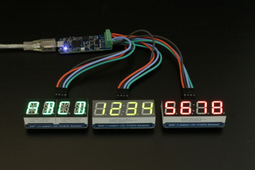
The same thing in real life
However, make sure not to go above the power limit (~200mA) that the Yocto-I2C can deliver, or use an external power supply.
Conclusion
When you understand how these alphanumeric HT16K33-based displays work, it's relatively easy to write code enabling you to drive them from a Yocto-I2C. We even wrote you a complete class in Python which enables you to drive Adafruit 7-segment and 14-segment displays, but also 8x8 et 16x8 matrices based on the same chip. If Python is not your preferred language, the code is short and simple enough for you to translate it easily.
A last comment: Adafruit displays are supposed to work in 3.3V as well as 5V, but we noticed that when we powered them in 5V while communicating in 3.3V, as the Yocto-I2C allows us to do, the displays had a tendency to crash. We didn't take the time to investigate but they work perfectly well in 3.3V, at the cost of a slight decrease in brightness.


