Micro-USB-Hub-V2 : User's guide
2. Presentation
2.1 Double power supply 2.2 Power selection 2.3 Activity Led 2.4 USB power distribution 2.5 Electromagnetic compatibility (EMI) 2.6 Limitations 3. Interconnection
3.1 Connecting Yoctopuce modules 3.2 Direct soldering of ribbon cable 3.3 Direct soldering on the up port 3.4 Minimal size 4. Characteristics
5. Index
1. Introduction
The Micro-USB-Hub-V2 is a very small USB hub (42x28mm) allowing do-it-yourself enthusiasts to connect up to four USB 2.0 peripherals to a single USB cable. It was conceived to be placed inside devices, while taking up a minimum of space. This hub was designed mainly to connect Yoctopuce modules, but it can very well be used with other USB 2.0 Hi-Speed, Full-Speed, or Low-Speed peripherals. The Micro-USB-Hub-V2 is a multi-TT hub, this allows better performance than a regular single TT hubs when several USB 1.1 devices, such a Yoctopcue products, are connected.
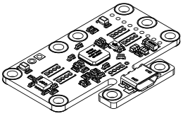
The Micro-USB-Hub-V2
Yoctopuce thanks you for buying this Micro-USB-Hub-V2 and sincerely hopes that you will be fully satisfied with it. The Yoctopuce engineers have put a large amount of effort to ensure your Micro-USB-Hub-V2 is easy to install anywhere.If you are nevertheless disappointed with this product, do not hesitate to contact Yoctopuce support. 1
2. Presentation
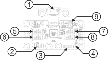
| 1: | USB Micro B connector (up port) | 6: | Down port 2 |
| 2: | Activity led | 7: | Down port 4 |
| 3: | External power supply connector | 8: | Down port 3 |
| 4: | External power led | 9: | Power selection |
| 5: | Down port 1 |
2.1. Double power supply
Your Micro-USB-Hub-V2 is able to manage a double power supply. You can simply connect the Micro-USB-Hub-V2 as is to your computer, and your computer is then responsible to provide the power necessary to supply the whole. In this case, be aware that a USB port does not supply more than 500mA, theoretically. To follow the rules, you can provide a 5V power supply on the contacts designed for this on the Micro-USB-Hub-V2. Peripherals connected to the hub are then supplied by this external power supply. Warning: Make sure to get the correct polarity when you connect your power supply, otherwise you risk to destroy your hub and the USB peripherals connected to it.
Commutating from the USB bus power supply and the external power supply is performed automatically, depending on the presence of voltage on the external power supply. In the opposite to traditional USB hubs, commutating power supply is not based on a mechanical contact in the power socket. Thus, commutating power supplies does not depend only on the presence of a connector. The led sitting right next to the external power port will shine if then the hub is running on external power.
2.2. Power selection
One can force the hub to use external power by bridging the two contacts marked "bridge to force ext. power". This feature available starting from revision B.
2.3. Activity Led
The activity led will shine when devices are detected on any down port. If no device is present, then the activity led will stay off and the hub will go to sleep mode to spare power.
2.4. USB power distribution
Although USB means Universal Serial BUS, USB devices are not physically organized as a flat bus but as a tree, using point-to-point connections. This has consequences on power distribution: to make it simple, every USB port must supply power to all devices directly or indirectly connected to it. And USB puts some limits.
In theory, a USB port provides 100mA, and may provide up to 500mA if available and requested by the device. In the case of a hub without external power supply, 100mA are available for the hub itself, and the hub should distribute no more than 100mA to each of its ports. This is it, and this is not much. In particular, it means that in theory, it is not possible to connect USB devices through two cascaded hubs without external power supply. In order to cascade hubs, it is necessary to use self-powered USB hubs, that provide a full 500mA to each subport.
In practice, USB would not have been as successful if it was really so picky about power distribution. As it happens, most USB hub manufacturers have been doing savings by not implementing current limitation on ports: they simply connect the computer power supply to every port, and declare themselves as self-powered hub even when they are taking all their power from the USB bus (in order to prevent any power consumption check in the operating system). This looks a bit dirty, but given the fact that computer USB ports are usually well protected by a hardware current limitation around 2000mA, it actually works in every day life, and seldom makes hardware damage.
What you should remember: if you connect Yoctopuce modules through one, or more, USB hub without external power supply, you have no safe-guard and you depend entirely on your computer manufacturer attention to provide as much current as possible on the USB ports, and to detect overloads before they lead to problems or to hardware damages. When modules are not provided enough current, they may work erratically and create unpredictable bugs. If you want to prevent any risk, do not cascade hubs without external power supply, and do not connect peripherals requiring more than 100mA behind a bus-powered hub.
In order to help you controlling and planning overall power consumption for your project, all Yoctopuce modules include a built-in current sensor that indicates (with 5mA precision) the consumption of the module on the USB bus.
Note also that the USB cable itself may also cause power supply issues, in particular when the wires are too thin or when the cable is too long 2. Good cables are usually made using AWG 26 or AWG 28 wires for data lines and AWG 24 wires for power.
2.5. Electromagnetic compatibility (EMI)
Connection methods to integrate the Micro-USB-Hub-V2 obviously have an impact on the system overall electromagnetic emissions, and therefore also impact the conformity with international standards.
When we perform reference measurements to validate the conformity of our products with IEC CISPR 11, we do not use any enclosure but connect the devices using a shielded USB cable, compliant with USB 2.0 specifications: the cable shield is connected to both connector shells, and the total resistance from shell to shell is under 0.6Ω. The USB cable length is 3m, in order to expose one meter horizontally, one meter vertically and keep the last meter close to the host computer within a ferrite bead.
If you use a non-shielded USB cable, or an improperly shielded cable, your system will work perfectly well but you may not remain in conformity with the emission standard. If you are building a system made of multiple devices connected using 1.27mm pitch connectors, or with a sensor moved away from the device CPU, you can generally recover the conformity by using a metallic enclosure acting as an external shield.
Still on the topic of electromagnetic compatibility, the maximum supported length of the USB cable is 3m. In addition to the voltage drop issue mentionned above, using longer wires would require to run extra tests to assert compatibility with the electromagnetic immunity standards.
2.6. Limitations
Like all hubs on the market, the Micro-USB-Hub-V2 declares to the computer that it is self-supplied, whether there is an active external power supply or not. Doing so prevents the computer to which the hub is connected from deciding to limit the power of the peripherals that are connected to it to 100mA for each port, which would generally render them unusable.
Moreover, as on most USB hubs on the market, this hub does not contain electronics to limit the power consumption on down ports.
3. Interconnection
The Micro-USB-Hub-V2 is not equipped with connectors on the down ports: you must directly solder wires or connectors on the transversal contacts designed for this. This considerably reduces the space needed compared to a USB socket and the plug that fits in it. With the Micro-USB-Hub-V2, there are numerous connection methods.
3.1. Connecting Yoctopuce modules
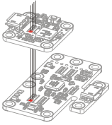
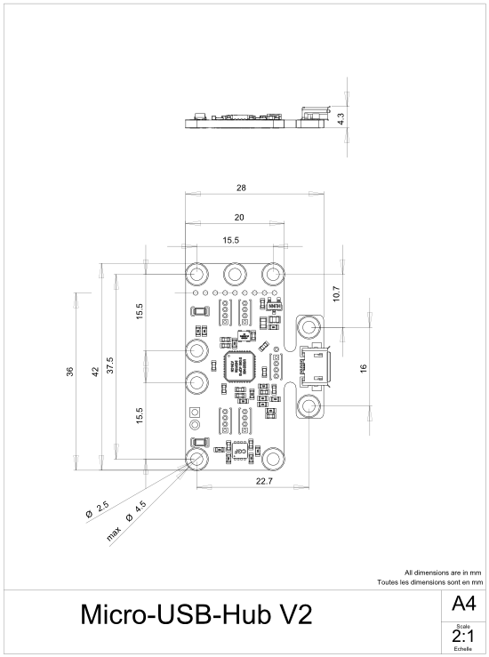
The Micro-USB-Hub-V2 is designed to allow you to connect up to four Yoctopuce modules, fixing them with screws and spacers. You will obtain a small compact block which will likely fit into your project. Use M2.5 screws with a head diameter of no more than 4.5mm. You can find such spacers and screw on Yoctopuce shop under the reference Fix-2.5mm. For the USB connection between the modules and the hub, you can solder electric wires, but the most practical solution is to solder headers with 1.27 pitch, available on Yoctopuce shop under the reference Board2Board-127. Alternatively, you can use small cables and connectors available under the reference 1.27-1.27-11.
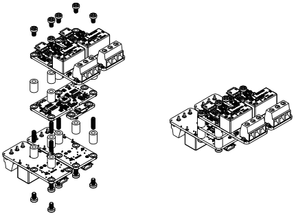
Assembly of Yoctopuce modules with screws and spacers.
Using headers for board to board connection
Warning: the connector is symmetrical and thus does not have a polarizator: do not connect the modules the other way around, or you will damage them forever. To help you, the connecting contacts of the USB modules have all a square pad at one end, corresponding to the ground of the USB bus. The square pads must coincide when connecting.
Beware of the direction of the connection!
3.2. Direct soldering of ribbon cable
You can decide to connect your peripherals with 1.27mm ribbon cable. Choose solid copper cable, this cable is less supple than a threaded one, but much easier to solder. Get the direction right: square pads must coincide.
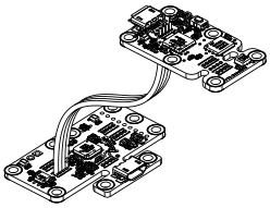
You can solder ribbon cables.
3.3. Direct soldering on the up port
If you believe that the Micro-USB-Hub-V2 takes too much room in your project, you can eliminate the up port connector, and solder a USB cable instead: cut the printed circuit with the help of a good pincer and, if needed, sandpaper the protruding parts. You only need then to solder the cable on the contacts designed for this. Caution: Get the direction right: orientation of the pad on the up port is the other way around compared to the neighboring down ports. You can solder the shield of the USB cable on the pad designed for it, right next to the contacts for the wire.
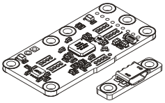
Eliminate the up port connector...
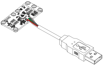
... and solder a USB cable instead.
| Connection | Wire | Pad | |
|---|---|---|---|
| USB Vcc | [ + ] | red | round |
| Data- | D- | white | round |
| Data+ | D+ | green | round |
| USB Vss | [ - ] | black | square |
3.4. Minimal size
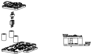
It is possible to lower the size of the Micro-USB-Hub-V2 down to 20x36mmmm by cutting one of its ends. This allows you to slip it into the most tiny locations, but you will loose the the possibility to screw four Yoctopuce modules on it.
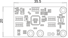
How to render the Micro-USB-Hub-V2 as small as possible.
4. Characteristics
You can find below a summary of the main technical characteristics of your Micro-USB-Hub-V2 module.
| Product ID | MHUB0002 |
| Hardware release† | Rev. D |
| USB connector | micro-B |
| Width | 28 mm |
| Length | 42 mm |
| Weight | 4 g |
| Chipset | Microchip USB2514BI (USB 2.0) |
| Normal operating temperature | 5...40 °C |
| Extended operating temperature‡ | -30...85 °C |
| RoHS compliance | RoHS III (2011/65/UE+2015/863) |
| USB Vendor ID | 0x0424 |
| USB Product ID | 0x2514 |
† These specifications are for the current hardware revision. Specifications for earlier revisions may differ.
‡ The extended temperature range is defined based on components specifications and has been tested during a limited duration (1h). When using the device in harsh environments for a long period of time, we strongly advise to run extensive tests before going to production.
5. Index
Ttechspec U
usbcurrent
