![]() This week, we present you a new module which completes our range of electrical interfaces. The Yocto-I2C enables you to interface many quite useful small electrical circuits. We know that some of you were waiting for it impatiently...
This week, we present you a new module which completes our range of electrical interfaces. The Yocto-I2C enables you to interface many quite useful small electrical circuits. We know that some of you were waiting for it impatiently...
I2C buses are very common in digital electronics: many peripheral electronic circuits are provided with this interface: sensors, memories, small screen, and so on... The main interest of I2C compared to its direct competitor, SPI, is that it requires only four wires, including power supply. To tell you the truth, many Yoctopuce modules use I2C sensors.
The Yocto-I2C
The Yocto-I2C is a 50x20mm module. It has an I2C port which can work at will with 3.3V or 1.8V. It also has an additional power supply which can provide 5V, 3.3V, or 1,8V. So you can, if necessary, power your device with a different voltage than that of the I2C bus, which is a rather common occurrence.
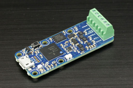
The Yocto-I2C
As for all our electrical digital interfaces, not only can you drive the Yocto-I2C directly from your program, but you can also use the embedded job system to present the results in the way of a Yoctopuce sensor, with all the advantages that go with it: callbacks, data logger, calibration, and so on...
You may have noticed that the Yocto-I2C is not supposed to work directly with a 5V I2C bus. We made that design choice not only for technical reasons, but also because 5V I2C devices are not that common. Not to mention that a slave I2C port designed to work in 5V may very well work as well is 3.3V. In the worst case, you can work around the issue by inserting a level shifter.
Note, the Yocto-I2C is designed to behave as an I2C master, you can't use it to emulate an I2C slave. However, you can perfectly well drive several I2C slaves with the same module as long as these slaves work with the same voltage and have distinct I2C addresses.
Application examples
Here are some very simple application examples.
DS3231 RTC module from Adafruit
Adafruit commercializes a small breakout board hosting a Real Time Clock (RTC) chip DS3231 from Maxim.
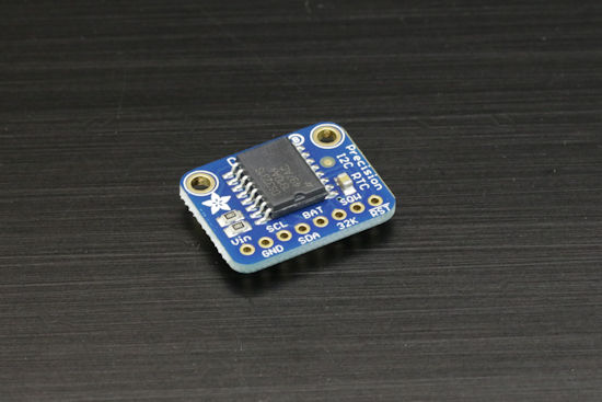
The DS3231 on the Adafruit breakout board
Interfacing this chip with a Yocto-I2C is a good exercise. The I2C address of the chip is 0x68, seconds, minutes, hours, day of the week, day of the month, month, and year on two digits are stored in BCD in registers 0x00 to 0x06, with a small twist: the century change (1900 -> 2000) is stored in bit 7 of register 5. Here is a Python example which sets the RTC and then reads it again every second.
from yocto_api import *
from yocto_i2cport import *
def getRtcTime(i2cPort):
i2cdata = [0x00] # start at register 0
buff = i2cPort.i2cSendAndReceiveBin(0x68,i2cdata,7)
s = (buff[0] & 0xf) + 10*(buff[0]>>4)
m = (buff[1] & 0xf) + 10*(buff[1]>>4)
h = (buff[2] & 0xf) + 10*(buff[2]>>4)
D = (buff[4] & 0xf) + 10*(buff[4]>>4)
M = (buff[5] & 0xF) + 10*((buff[5] & 0x70)>>4)
Y= (buff[6] & 0xF) + 10*(buff[6]>>4) +1900
if (buff[5] &0x80)!=0: Y=Y+100
return datetime.datetime(Y,M,D,h,m,s)
def setRtcTime(i2cPort):
i2cdata = []
now = datetime.datetime.now()
centuryBit =0x00
if (now.year>=2000): centuryBit=0x80
i2cdata.append(0) # start at register 0
i2cdata.append( (now.second %10) | ((now.second //10)<<4))
i2cdata.append( (now.minute %10) | ((now.minute //10)<<4))
i2cdata.append( (now.hour %10) | ((now.hour //10)<<4))
i2cdata.append( now.weekday() )
i2cdata.append( (now.day %10) | ((now.day //10)<<4))
i2cdata.append( (now.month %10) | ((now.month //10)<<4) | centuryBit)
i2cdata.append( ((now.year %100) %10) | (((now.year %100) //10)<<4))
i2cPort.i2cSendBin(0x68,i2cdata)
# init API
errmsg = YRefParam()
if YAPI.RegisterHub("usb", errmsg) != YAPI.SUCCESS:
sys.exit("init error" + errmsg.value)
# find I2C port
i2cPort = YI2cPort.FirstI2cPort()
if i2cPort is None:
sys.exit('No module connected (check cable)')
# configure I2C Port
i2cPort.set_i2cMode("400kbps")
i2cPort.set_i2cVoltageLevel(YI2cPort.I2CVOLTAGELEVEL_3V3);
setRtcTime(i2cPort)
while True:
YAPI.Sleep(1000,errmsg)
print(getRtcTime(i2cPort))
Lidar-Lite V3, from Garmin
The Lidar-Lite V3, commercialized by Garmin, is a small laser telemeter which can measure distances up to 40 meters. On top of an analog interface, it has an I2C interface.
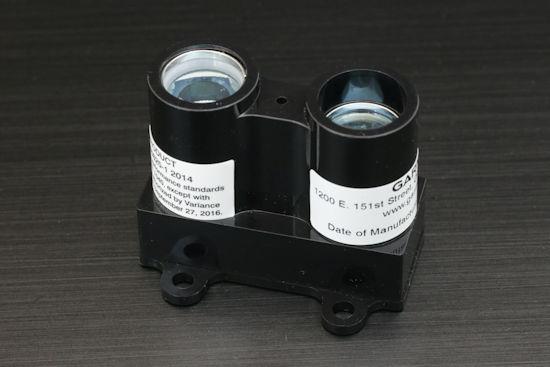
The Garmin Lidar-Lite V3
Officially, the Lidar-Lite V3 works in 5V, but as long as the wires are not too long, it works very well if you power it with 5V while you use 3.3V for the I2C bus.

Configuration of the I2C port for the Lidar-Lite V3
The I2C address of the Lidar-Lite V3 is 0x62. To obtain a measure, one must write 0x04 in register 0x00, wait for bit 0 of register 0x01 to go to zero, then read the distance in cm, coded over two bytes in register 0x8f. You can easily take advantage of the job system of the Yocto-I2C to read the value of the sensor and to map it for example on Generic Sensor 1 of the module. You can do so with a job made of three tasks:
- Task 1 (periodic, once, initialization)
- assert !isset($state)
- compute $state = 0
- Task 2 (periodic, 200ms, to trigger the measure)
- assert $state == 0
- writeLine @62:0004
- expect 62:{A}{A}{A}
- compute $state = 1
- Task 3 (periodic, 50ms, to wait for the result)
- assert $state == 1
- writeLine@62:01xx
- expect 62:{A}{A} 62:{A}($ready:BYTE)
- assert($ready & 1) == 0
- writeLine @62:8Fxxxx
- expect 62:{A}{A} 62:{A}($1:WORDB)
- $state = 0

Job definition to read the Lidar-Lite
Adafruit 0.8" 8x16 LED Matrix display
Adafruit commercializes a small display, based on two 8x8 led matrices, driven by an HT16K33 chip working in 3.3V.
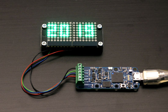
Use with the small Adafruit 0.8" 8x16 LED Matrix display
After a small initialization sequence, on only needs to write a 16 bytes series starting at register 0x00 to see them displayed on the leds. Note, the bytes are mapped vertically and they are interlaced. So the display function looks more like a cabalistic formula than to a demo example. Here is a small demo which displays an arbitrary integer between 0 and 9999.
from yocto_i2cport import *
def HT16K33_init(i2cPort):
#clock enable, ROW/IN is a led ouput,dimming 16/16,blinking off, display off
i2cdata = [0x21,0xA0,0xEF,0x80]
for i in range(0,4) : i2cPort.i2cSendBin(0x70, [i2cdata[i]])
#clean display buffer
i2cdata = [0] * 17
i2cPort.i2cSendBin(0x70, i2cdata)
#blinking off, display on
i2cdata = [0x81]
i2cPort.i2cSendBin(0x70, i2cdata);
def HT16K33_display_value(i2cPort,value):
value=int(value)
if value<0: value=0
font= [0x3e223e,0x3e0000,0x2e2a3a,0x3e2a22,0x38101e, # digits 0..9
0x3a2a2e,0x3a2a3e,0xe3202,0x3e2a3e,0x3e2a2e]
i2cdata = [0] * 17 # empty memory buffer
for x in range(0,4):
digit = value % 10
value= value//10
for j in range(0,4):
i2cdata[1+2*j+(x*17//2&0xf)]= (font[digit] >> 8*(3-j) ) & 0xff;
i2cPort.i2cSendBin(0x70, i2cdata);
# init API
errmsg = YRefParam()
if YAPI.RegisterHub("usb", errmsg) != YAPI.SUCCESS:
sys.exit("init error" + errmsg.value)
# find I2C port
i2cPort = YI2cPort.FirstI2cPort()
if i2cPort is None:
sys.exit('No module connected (check cable)')
# configure I2C Port
i2cPort.set_i2cMode("400kbps")
i2cPort.set_i2cVoltageLevel(YI2cPort.I2CVOLTAGELEVEL_3V3);
HT16K33_init(i2cPort)
for i in range (0,10000):
HT16K33_display_value(i2cPort,i)
YAPI.Sleep(100,errmsg)
Even better ...
As you can put several I2C slaves on the same I2C bus, nothing prevents you from putting the two preceding examples together.
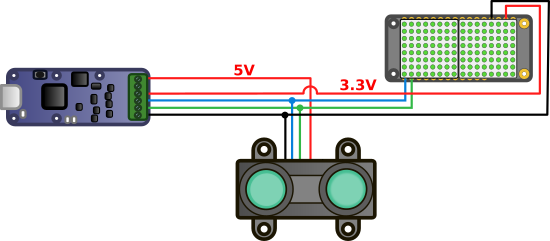
The Adafruit display and the Lidar-Lite on the same I2C bus
The idea is simply to read the Lidar-Lite's values that the Yocto-I2C has mapped on genericSensor1 and to display them:
i2cPort = YI2cPort.FirstI2cPort()
if i2cPort is None:
sys.exit('No module connected (check cable)')
serial = i2cPort.get_module().get_serialNumber()
power = YPowerOutput.FindPowerOutput(serial+".powerOutput")
power.set_voltage(YPowerOutput.VOLTAGE_OUT5V); # power the Lidar-Lite
sensor = YGenericSensor.FindGenericSensor(serial+".genericSensor1")
# configure I2C Port
i2cPort.set_i2cMode("400kbps")
i2cPort.set_i2cVoltageLevel(YI2cPort.I2CVOLTAGELEVEL_3V3);
# start the LIDAR handling job on the device
# result is mapped on generic sensor #1
i2cPort.set_currentJob("lidar.job")
HT16K33_init(i2cPort)
while True:
value =sensor.get_currentValue()
HT16K33_display_value(i2cPort,value)
YAPI.Sleep(200,errmsg)
And here is the result:
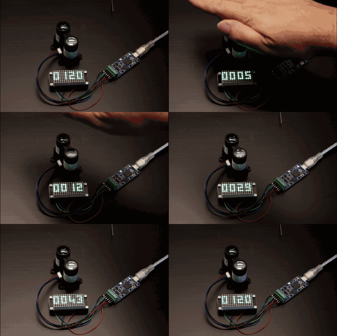
Two devices on the same I2C bus
Note intended for beginners
If you have never interfaced an I2C device before, you may be tempted to believe that you only need to connect it to a Yocto-I2C for the data to magically appear. Yoctopuce products are pretty plug-and-play, but not up to this point. Unfortunately, you'll have to carefully study the datasheet of the device that you want to use to understand and implement its I2C protocol. The base principle of I2C protocols is always the same, but each interface has its specificities. Note that the quality of a component and that of its datasheet are often closely linked. Time spent in carefully studying a datasheet before selecting a component is likely to be rewarded by a smooth implementation... don't say we didn't warn you :-)
Conclusion
Most development computers, such as Raspberry Pi, Beaglebone, Arduino, and so on, already have I2C ports that are available to the user. Now you can do the same from a classic computer, and as always, without having to install any driver :-)


