![]() Someone recently asked us how to interface an AMS TSL2591 ambient light sensor with the Yocto-I2C. It's an interesting question for two reasons: the TSL2591 is considerably more sensitive in low light than the Yocto-Light-V2 or the Yocto-Light-V3 and more particularly its I2C protocol is not the simplest to implement. It's an opportunity to test the limits of the Yocto-I2C autonomous job system.
Someone recently asked us how to interface an AMS TSL2591 ambient light sensor with the Yocto-I2C. It's an interesting question for two reasons: the TSL2591 is considerably more sensitive in low light than the Yocto-Light-V2 or the Yocto-Light-V3 and more particularly its I2C protocol is not the simplest to implement. It's an opportunity to test the limits of the Yocto-I2C autonomous job system.
This post assumes that you already have some knowledge of how I2C interfaces work. If it is not the case, we recommend that you read the appropriate chapter in the Yocto-I2C documentation.
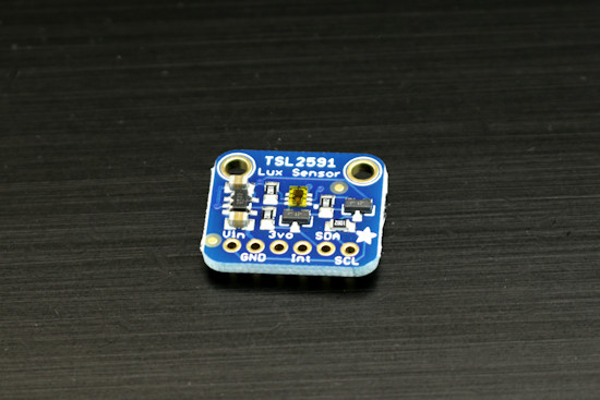
The TSL2591, Adafruit version
The TSL2591 that we have on hand is already soldered on a small PCB sold by Adafruit. We only need to connect it to the Yocto-I2C.

Connection to the Yocto-I2C
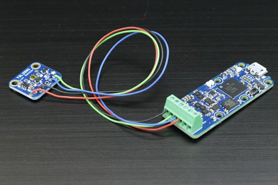
The same in real life
That was the easy part. Now, we must configure the Yocto-I2C so that it can communicate with the TSL2591, and to do so we must start by carefully study the TSL2591 datasheet.
Configuration
By reading this document, we note that:
- The sensor works between 2.7V and 3.6V. We can therefore power it in 3.3V without risk and we don't need the auxiliary power supply (aka powerOutput) of the Yocto-I2C.
- The I2C protocol of the sensor can go up to 400kHz, but we can perfectly work with a standard speed of 100kHz. In electronics, going faster than required is often counterproductive.
- The datasheet doesn't mention whether the sensor supports the restart condition. In doubt, we are going to use classic stop/start.
- The other parameters can stay at standard values.
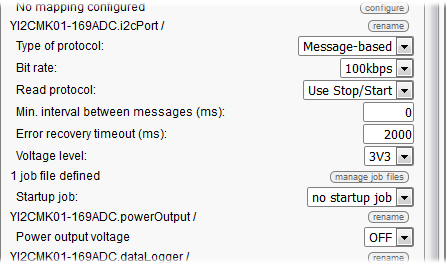
Configuration of the Yocto-I2C in the VirtualHub
Writing the I2C communication job
We now need to write an autonomous job which is going to automatically query the sensor, and for this we need to study the datasheet in more depth. We learn there that:
- The address over 7 bits of the sensor is 0x29. The first byte of each I2C transfer is therefore 0x29 * 2 = 0x52 to write et 0x29 * 2 + 1= 0x53 to read.
- The addresses of the I2C registers are stored in the 5 less significant bits of the command register, the three other bits staying most of the time at 0b101. The command to access register 0 is therefore 0b10100000 = 0xA0, the command to access register 1 is 0xA1, and so on...
- Incremental addressing is supported, if you perform two read operations one after the other without touching the command register, you obtain the values of two adjacent registers.
- At start up, the sensor doesn't perform any measure. To trigger the measures, you must set to 1 bits 0 and 1 of register 0, the others can stay at zero.
- By default, all the measures are performed at 10Hz, that is a result every 100ms.
- The result of the measures is given in counts, not in lux.
- The result for the measure of white light (CH0) is stored in register 0x14 (LSB) and 0x15 (MSB), coded over 16 bits, in other words over a WORD in little endian.
- At 10Hz, the value of CH0 can vary between 0 and 37888, and not 65535 as we could expect it.
- There are four gain settings, stored in bits 4 and 5 of register 1. These settings correspond to the x1, x25 , x428, and x9876 factors.
The different I2C commands that we will need are therefore:
- {S}52A003{P} to start the sensor
- {S}52A1{P}{S}53xx{N}{P} to read the gain
- {S}52B4{P}{S}53xx{A}xx{N}{P} to read the value of channel 0
- {S}52A100{P} to set the gain to 0
- {S}52A110{P} to set the gain to 1
- {S}52A120{P} to set the gain to 2
- {S}52A130{P} to set the gain to 3
To manage all this, we need a $state state variable and a $gain variable to remember the current gain value. We propose to write a job with the following structure:

Job structure to query the TSL2591
Which is translated by the following tasks, which are executed depending on the state of the $state variable:
- Task "init", periodic once:
- assert ! isset($state)
- writeLine {S}52A003{P}
- expect 29:{A}{A}{A}
- writeLine {S}52A1{P}{S}53xx{N}{P}
- expect 29:{A}{A} 29:{A}($gain:BYTE)
- compute $gain=($gain>>4)&3
- compute $state=1
- log Init Done
- Task "read", periodic every 100ms:
- assert isset($state)
- assert $state=1
- writeLine {S}52B4{P}{S}53xx{A}xx{N}{P}
- expect 29:{A}{A} 29:{A}($CH0:WORDL)
- compute $1 = ($gain==0 ? $CH0*9.876 : ($gain==1 ? $CH0*0.428 : ($gain==2 ? $CH0*0.025 : $CH0*0.001 )))
- compute $state = ( $CH0<50 && $gain<3 ? 2 + $gain +1 : $state)
- compute $state = ( $CH0>37000 && $gain>0 ? 2+$gain-1 : $state)
- Task "setGainTo0", periodic every 100ms:
- assert isset($state)
- assert $state==2
- writeLine {S}52A100{P}
- expect 29:{A}{A}{A}
- compute $gain=0
- log gain set to 0
- wait 200
- compute $state=1
- Task "setGainTo1", periodic every 100ms:
- assert isset($state)
- assert $state==3
- writeLine {S}52A110{P}
- expect 29:{A}{A}{A}
- compute $gain=1
- log gain set to 1
- wait 200
- compute $state=1
- Tāche "setGainTo2", periodic every 100ms:
- assert isset($state)
- assert $state==4
- writeLine {S}52A120{P}
- expect 29:{A}{A}{A}
- compute $gain=2
- log gain set to 2
- wait 200
- compute $state=1
- Task "setGainTo3", periodic every 100ms:
- assert isset($state)
- assert $state==5
- writeLine {S}52A130{P}
- expect 29:{A}{A}{A}
- compute $gain=3
- log gain set to 3
- wait 200
- compute $state=1
The business end the job are the last three lines of the "read" task: we have read the CH0 register which we multiply by the factor corresponding to the current gain, divided by 1000 to avoid an overflow, and we assign the result to the genericSensor1 of the Yocto-I2C. If the value of channel CH0 is smaller than 50 or greater than 37000, we decide to correct the gain by computing a new value of $state, which triggers the execution of the corresponding setGainToX task. Note that after changing the gain, we wait for 200ms, as we noticed that changing the gain distorts the value of the current measure. You can note that there is a setGainToX per gain value, because the Yocto-I2C jobs do not allows variable use in I2C transfers.
You can download the ready-made le job here. Once you have uploaded it on the file system of your Yocto-I2C, you can start it directly from the VirtualHub interface. If you want the job to automatically start with the module, you only need to modify the "Startup job" configuration setting of your Yocto-I2C accordingly.
Count vs Lux
With this job, you get the measured valued stored in genericSensor1 of the Yocto-I2C. Unfortunately, this value in given in count and not in lux. The TSL2591 datasheet only suggests to use an "empirical formula" to make the conversion. By comparing with a calibrated luxmeter, we noticed that for measures performed at 10Hz, we only needed to divide the number of counts by two to obtain values similar to those of the luxmeter. Rather than hard coding this division in the protocol, we preferred storing it in the GenericSensor1 mapping.
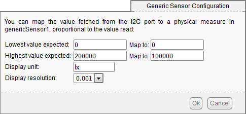
count=> lux conversion in the sensor mapping
The interest of performing the conversion in this location is that it is easy to modify later on. Indeed, the min/max values of the "ADC count value" described in figure 9 of the datasheet make us think that there can be important differences from one sensor to another.
Conclusion
Interfacing an I2C sensor is not always easy, but using the Yocto-I2C allows you, when you have written the corresponding job, to read the values of an I2C sensor as easily as if it were a native Yoctopuce sensor. The proof: here are the measures of the TSL2591 displayed directly in Yocto-Visualisation.
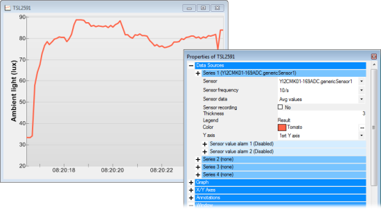
Values of the TSL2591 in Yocto-Visualization


