 We have been asked several times whether we were going to manufacture a color sensor, also known as a RGB sensor. To be honest, the answer is: "we don't really know". You are about to understand why: this week, we are going to interface the TAOS TCS34725 color sensor with a Yocto-I2C.
The easiest way to test the TCS34725 sensor is probably to use the matching Adafruit breakout board and that's what we did.

The TCS34725 sensor mounted on an Adafruit PCB
Connections
The I2C connection is rather easy, you can power the board with 3.3V. On top of the TCS34725, the board features a white led. By default, the led is on. To turn it off, you must force the led input to 0V, but the Yocto-I2C doesn't have an open-drain output. However, there is a trick to use the PWR output of the Yocto-I2C. The led is driven by a mosfet which input is drawn to 3.3V with a 10KΩ resistor.
")
The led is kept on with a pull-up of 10K (source: Adafruit)
One can counteract this 10KΩ pull-up with a 1KΩ pull-down, so that the led is off by default and can be turned on with the PWR output of the Yocto-I2C. You only need to set it to 1.8V or 3.3V to turn the led on.

Connecting to the Yocto-I2C while driving the LED
If you don't need the led, simply connect the led input to GND.
Protocol
The I2C address of the TCS34725 is 0x29: each write message therefore starts with the 0x52 byte and each read message starts by 0x53. The second byte is a command byte with its bit 7 always set to 1. Bits 6 and 5 are used to define, among other things, whether the address pointer must be automatically incremented. Bits 4 to 0 define the address to be used.
Initialization
By default, the sensor is sleeping. You must turn it on by setting to 1 bits PON and then AEN of register 0. Be careful to respect a 2.4ms delay between the two. You must also define the frequency at which the sensor must sample. Setting 0xd5 in register 0x01 gives a 101 ms period. The initialization task thus looks like this:
writeLine {S}528001{P} wait 10 writeLine {S}528003{P} writeLine {S}5281D5{P} compute $init_done=1
Reading
Synchronization between the initialization task and the reading task is managed by the init_done variable. When the initialization is performed, you must then read the data starting from register 0x13, making sure that the pointer automatically increases, hence the 0xB3 value for the command register. The data are, in order, the status byte with bit 0 indicating if the latest conversion went well, then the values for white, red, green, and blue light encoded as 16 bit words, with the least significant byte first. The reading task querying the sensors and mapping the result on genericsensors 1 to 4 looks therefore like this:
assert isset($init_done) writeLine {S}52B3{P}{S}53xx{A}xx{A}xx{A}xx{A}xx{A}xx{A}xx{A}xx{A}xx{N}{P} expect 29:{A}{A} 29:{A}($S:BYTE)($C:WORDL)($R:WORDL)($G:WORDL)($B:WORDL) assert ($S & 1) ==1 compute $4=$C compute $1=$R compute $2=$G compute $3=$B
Results
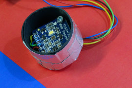
We placed the sensor about 4 cm above a piece of paper with large squares of solid colors and we tried three distinct levels of lighting: ambient light, lighting with the embedded white led, and lighting with a powerful light.

Our experimental setup
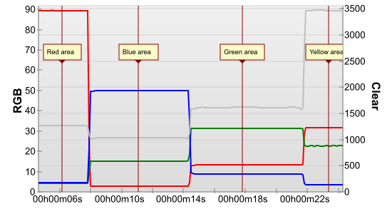
At first sight, the sensor works as expected. If you orient it above the red surface, you clearly see a red dominant in the results measured by the sensor. You also notice that on values for green and blue are clearly not to zero. The more light we have, the higher the values.

Three levels of lighting on a red surface
However, the sensor is having trouble to distinguish the blue color, at some levels it even sees more red than blue

Three levels of lighting on a blue surface
It is clear that the level of lighting greatly influences the result: the more you light the surface, the higher the values we obtain, although the surface itself didn't change. It's rather logical as the sensor in fact measures the light that reaches it: the more light, the more our surface reflects it, and the more our sensor is going to get.
But this illustrates the issue with this type of sensor: it's difficult to exactly map the values of the sensor with a set color. However, you can try to take advantage of the fact that the sensor has a channel which measures white light and try to normalize the RGB values by comparing them to the white channel. The library provided by Adafruit does just that. The code divides the value of each channel by the value of the white light, limits the results between 0 and 1.0, puts everything to the power of 2.5 to compensate the lack of linearity of the sensor, and multiplies everything by 255. We can modify our job so that it does the same thing:
assert isset($init_done) writeLine {S}52B3{P}{S}53xx{A}xx{A}xx{A}xx{A}xx{A}xx{A}xx{A}xx{A}xx{N}{P} expect 29:{A}{A} 29:{A}($S:BYTE)($C:WORDL)($R:WORDL)($G:WORDL)($B:WORDL) assert ($S & 1) ==1 compute $4=$C compute $R=$C>0?$R/$C:0 compute $R=$R<=1?$R:1 compute $R=255*($R**2.5) compute $G=$C>0?$G/$C:0 compute $G=$G<=1?$G:1 compute $G=255*($G**2.5) compute $B=$C>0?$B/$C:0 compute $B=$B<=1?$B:1 compute $B=255*($B**2.5) compute $1=$R compute $2=$G compute $3=$B
Thus, we obtain a slightly better color differentiation, but this adds other side-effects:

Three levels of lighting on a red surface, normalized results
For red under strong lighting, as the white channel increases much faster than the red channel, we obtain a lower red level. And for blue, the algorithm amplified the issue with the intermediary lighting.

Three levels of lighting on a blue surface, normalized results
To find out for sure, we mounted the sensor in a small black cup to redo the experiment with a better controlled lighting: the only light source is the white led on the board. We moved our sensor around on the colored paper. The result is much more stable and allows us to easily know each dominant hue. But it also clearly shows that normalizing each channel is far from being ideal.
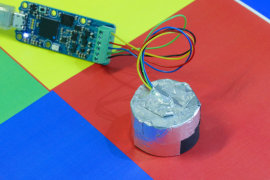
We performed the experiment again while controlling the lighting
Conclusion
We are not convinced so far. This type of sensor would probably work well to classify a set of predefined colors under a well controlled lighting, but it seems difficult to use it to recognize and reproduce with accuracy any color observed under an arbitrary lighting. You now understand why we are reticent to create a Yoctopuce module on its own right. This being said, we don't give up the idea: there may be color sensors easier to exploit. If you nevertheless want to use the TCS34725 with a Yocto-I2C, you can download the two jobs described in this post.

