 After last week's post on how to query an SPI sensor by explicitly managing SPI communications using the Yoctopuce library, we are now going to show how the Yocto-SPI can make your life even easier, and above all simplify the code of the application.
We are therefore keeping the same Murata SCL3300 precision inclinometer and we are going to show you how the communication protocol that we implemented in C# can be integrated directly inside the Yocto-SPI, so that the controlling computer is relieved of this task.
Step 1: Configuring the Yocto-SPI
The parameters that we configured by software can easily be configured in the web interface of the VirtualHub as well, it's up to you. Here is the interface when you have correctly set all the configuration parameters:

Yocto-SPI configuration for the SCL3300
If you have questions concerning the choice of the parameter values, you can come back to last week's post where we told you where to find the information in the sensor datasheet.
Step 2: Integrating the protocol into the Yocto-SPI
The aim of this step is that the Yocto-SPI spontaneously performs all the transmissions that we have implemented in C# previously. We are therefore going to define a Job in the module configuration interface. This job will contain several tasks, each responsible for one aspect of the protocol: initialization, configuration, check, measures. To give you an overview at first glance, here are the 7 tasks that we need to define. They are explained below.

The 7 tasks to communicate with the SCL3300
Note that we could have used a few shortcuts to make a simpler solution for our particular case, but we decided to show you a more general solution, that you can adapt to most sensors, in particular thanks to the use of a state variable.
The Reset task
When launching the Job, we start by emptying the communication buffer and by defining a $st state variable which enables us to know which other tasks can be run depending on the state of the sensor.

The initialization task
This task is performed only once, when the state variable hasn't been defined yet.
The SetMode4 task
This task performs the configuration of the SCL3300, such as described in table 10 of the datasheet. You can recognize the command setting the sensor in mode 4, the delays, and the command to read the status. Note that as for the C# approach, we choose to serialize the commands: everything is sent in one go, respecting specified timings, but the results of the commands are taken care of in a separate task.

The configuration task
This task is defined as periodical as we could need to reactivate it if for one reason or another the sensor needs to be reinitialized. We would then need only one other task to reset $st to zero, and the task would run again.
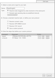
The CheckID task
The aim of this task is to check that initialization worked well. This time it is a reactive task, which means that it is spontaneously triggered in answer to the apparition of a given message sent by the SCL3300. The first command is therefore expect, which recognizes the answer of the READ_ID message with the expected CL identifier. If it is the case, we put a Sensor ready message in all the logs of the module and we switch to the state in which we can start querying the sensor.

The checking task
The QueryAngles task
Here is at long last the task that automatically triggers the reading of measures, serially like in C#. The task is periodic every 100ms, which enables us to read at 10Hz, in line with the specifications of SCL3300 mode 4.

The querying task
You'll note that there is no actual reading of the results in this task. As for the preceding CheckID task, we are going to use reactive tasks to decode received messages. Thus, you don't even need to plan for temporisation, the module automatically calls our task as soon as the answer arrives.
Note also that we must perform an additional query after asking for the Z angle to receive the answer, as answers in an SPI protocol are only transmitted when one sends the next message.
The ReadAnglesX/Y/Z tasks
We could have created only one task to read three consecutive answers, but as they're three different messages, we opted for a more generic behavior with three distinct tasks, without dependency on the order in which the axes are queried and the order in which the answers arrive.


The tasks reading the results
Note the computation which literally copies the definition given in the module datasheet and assigns it into the genericSensor1/2/3 functions through the $1, $2, and $3 variables.
Step 3: Live tests
When you have defined the job, you can run it to see the measures in the web interface of the VirtualHub live (using Show device functions button). The green led of the Yocto-SPI blinks at a rate of 10Hz, for each query.
You don't need anymore to communicate explicitly with the sensor through SPI messages in order to retrieve the sensor values by software: you only need to read the sensor value as you would for any other Yoctopuce sensor:
double angle_x = sensorX.get_currentValue()
You can also perform readings by value change callback or by timed report callback.
sensorX.registerTimedReportCallback(updateAngleX);
public void updateAngleX(YFunction f, YMeasure m)
{
angle_x = m.get_averageValue();
}
Naturally, you can also automatically store the measures in the flash memory of the module, and display them with Yocto-Visualization. By the way, we'll take this opportunity to compare the performances of this sensor to others... But that's for next week!

