 Electric circuits used in buildings for signalling and control have some specificities. When you know them, it is easy to drive them with Yoctopuce modules connected to a standard computer. This enables you to replace obsolete programmable logic controllers with systems much easier to program, while offering a much more modular solution than dedicated PCI interface cards.
When electricians must transmit a command through a building over a distance of several tens of meters, they don't (with rare exceptions) embarrass themselves with digital systems and checksums. The priority is placed on simplicity in order to ease maintenance: each command is transferred on a separate pair of wires.

An electrician control panel
This doesn't mean that there is no "digital" logic, on the contrary: each wire pair goes usually from an electrical enclosure to another, where signals can be combined using relays connected in parallel or in series. Two relays with outputs connected in series perform a logical "and", while two relays connected in parallel perform a logical "or". Negation is performed using normally-closed (NC) relays.

An excerpt of the panel diagram
On top of being simple and easy to diagnose (each relay usually includes a led indicating its state), the relay logic has the advantage of solving the issue of distinct electrical phases. Indeed, from one location to another inside a building, it's very likely that two electrical devices are not connected on the same phase. If you connect them without being careful, the 380V potential difference may instantaneously destroy the electronics. But relays are naturally isolated and therefore protected against this risk.
On large distances, as found in buildings, the wire resistance can easily reach 1 Ohm. In order to make it negligible, electricians usually work with tensions of 12V, 24V, or even 48V. Sometimes, they work with direct current (DC), some other times with alternative current (AC). As each signal serves usually to activate one relay, it carries typically between 20 and 50mA.
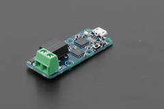
To interface a computer with this type of installation, the two most useful Yoctopuce modules are the Yocto-MaxiCoupler and the Yocto-Volt.
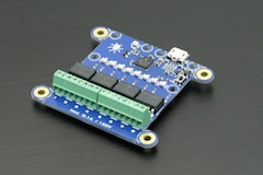
Appropriate Yoctopuce interface modules
The first one enables you to drive 8 independent relays, using the power supply directly provided by the electric panel. These octocouplers allow you to commute direct current as well as alternative current, in 12V, 24V, or even 48V. Each output contact pair in the device is electrically isolated, as it is always recommended for use in this kind of installation.
The Yocto-Volt enables you to detect a 12V, 24V, or 48V signal, in direct or alternative current. The module fully isolates the computer from the measured signal. However, for each signal you need to detect, you must use a distinct Yocto-Volt, as we don't (yet) have an isolated module with several inputs.
A real application
In the course of a recent hardware update on a monitoring system for a public swimming pool (drowning detection), we had to replace an old obsolete PCI interface card (which didn't work under Windows 7) by Yoctopuce modules. Yoctopuce modules, requiring no drivers, work therefore under all operating systems.

PCI interface card, not supported under Windows 7.
We had to manage 4 alarm outputs, 4 technical failure outputs, and one alarm validation input. All signals were using 24V. We have therefore used... a Yocto-MaxiCoupler and a Yocto-Volt. Because they are small, Yoctopuce modules easily fit inside a computer standard enclosure. Most computer motherboards (in our case it was an ASUS motherboard) include several additional USB ports which are not connected to the front panel. They can easily be used to connect the Yoctopuce modules without having USB cables visible outside of the computer. The magnet on the module enclosure easily keeps the device in place.

Connecting the Yoctopuce modules on an internal port of the computer
Once done, we only needed to bring all the signals to be exchanged with the electric panel to a single connector, at the back of the machine. In our case, we used a 37 pin Canon plug, cabled exactly like the old interface card we were replacing. And voila!

