 Creating a software to query an SPI sensor contains a number of traps, linked to the specificities of this communication mode. This post provides some advice to avoid the most frequent pitfalls.
We are going to take as example the Murata SCL3300 precision inclinometer, which you can buy directly soldered on a break-out board, as it is very convenient for running tests.

Break-out board for the SCL3300, with a Yocto-SPI interface
Step 1: Configuring the Yocto-SPI
Take the time to carefully read the datasheet or the sensor documentation, and don't hesitate to come back to them as many times as required. If you believe that there is an error in the datasheet, remember that this occurs only extremely rarely and that it's more likely a communication protocol issue that needs to be fixed.
To correctly implement the communication software, the first items you must look for in the datasheet are:
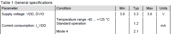
a. Supply and communication voltages, as well as the sensor current consumption. The Yocto-SPI can provide power supply at 3.3V (up to 200mA) or 5V (up to 450mA). For the SCL3300 sensor, these pieces of information are at two distinct locations.

We are therefore going to be able to power the sensor directly through the Yocto-SPI, which our software can configure as follows:
powerOutput.set_voltage(YPowerOutput.VOLTAGE_OUT3V3);
b.The minimal and maximal communication frequency which is supported. Always start with a low enough frequency while developing, to avoid accumulating potential problem sources. You can raise the speed later on when you are sure about what you are doing. Here are the specifications for our sensor:

We therefore use the 100KHz minimal frequency for development.
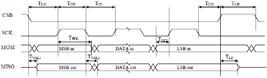
c. The SPI communication mode, corresponding to the clock synchronization convention. Sometimes the mode number is provided explicitly, sometimes it's the CPOL and CPHA polarities, sometimes it's only a communication diagram which is provided. Refer to the Wikipedia page if you have a doubt on the correspondences. Specifications for the Murata are very clear:
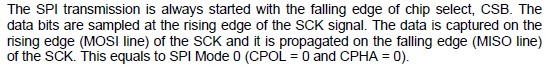
Note, the sensor can seem to be working with an incorrect mode, for example when the wrong clock polarity is used, but occasional communication errors will then occur.
d. The bit transfer order. Most of the time, it's the most significant bit (msb) which is transmitted first, but it is better to check.
By combining the three latter pieces of information, you can perform the basic configuration of the SPI communication:
e. SS line convention of use (Slave Select), sometimes called CS (Chip Select) or CSB (Chip Select Bar). For some sensors, this line only serves to multiplex several chips on the SPI bus but doesn't directly intervene in the communication protocol. For others, such as the Murata sensor, the CS line is used to separate messages (frames) and must imperatively be enabled and disabled for each group of four bytes. There must be a minimum delay of 10[us] between each message:

The Yocto-SPI can automatically drive the SS (CSB) line through messages: you only need to configure it in Frame mode and to indicate the minimal space that you want between the messages, as well as the SS line polarity:
spiPort.set_ssPolarity(YSpiPort.SSPOLARITY_ACTIVE_LOW);
Thus each write command sent on the SPI port enables the SS line, sends the requested bytes, and disables the SS line. But to do so, you must naturally take care to send the four bytes in one go and not one after the other. The return bytes also come back spontaneously by message, and use of the Frame protocol translates them automatically in hexadecimal format.
Step 2: understanding how the sensor communicates
Each SPI sensor follows a slightly different logic, but there are some principles common to almost all SPI sensors.
Access to SPI sensors is generally structured in the shape of registers that you can read or write. Some registers are used for the configuration of the sensor, while others contain the latest measures or indications on the state of the sensor. We therefore want to start by configuring the sensor by writing into its registers, and then continuously read the measure registers.
If it were an asynchronous serial link (RS232, RS485, and so on), it would be indeed as simple as that. But the specificity of SPI communication protocols is that each exchange is necessarily bidirectional: for each byte sent, one byte is inevitably sent back in return, likewise you can't read a byte without sending one. Moreover, as the sensor usually can't react instantaneously to a command while transmitting, the bytes that it sends are always the answer to the preceding message. This is illustrated in the Murata sensor datasheet:
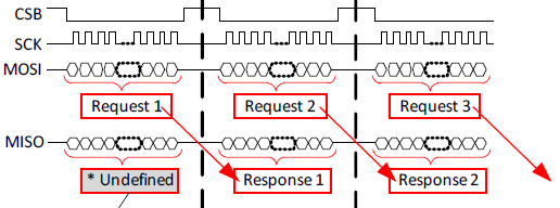
At the level of the protocol implementation, you must therefore take this into account, which gives the following code, for example, and which may seem confusing:
spiPort.writeHex(READ_ID); // requests the sensor ID
spiPort.readHex(4); // ignores the "1st answer"
spiPort.writeHex(READ_STATUS); // requests the status
string ID = spiPort.readHex(4); // reads the sensor ID
spiPort.writeHex(ANY_COMMAND); // triggers another frame
string status = spiPort.readHex(4); // reads the status
Note the use of the reset() method at the beginning to delete the content of the communication buffers in the module before the beginning of the operation. It's very important to avoid accidentally reading messages coming from the previous communications!
At this stage, you must still be careful with transmission delays, because the writeHex and readHex functions are non-blocking. In the case of writeHex, the frame to be sent is stored in the module send buffer and the call immediately gives back control, before sending is over. The next call to readHex is going to read the next 4 bytes of the read buffer, but only if the transmission has actually already happened. Otherwise, the call risks returning an empty string. There are several ways to solve this issue.
Solution 1: arbitrary delay. If you know how much time takes a transmission, you can simply add a call to YAPI.Sleep() to add a delay of a few milliseconds before each call to readHex. It's the simplest way, but not the most efficient one.
Solution 2: repeat the read operation. You can also code a function which calls readHex in a loop until it gets data. It may be faster than the preceding solution, but this creates an active wait, which is not the most efficient way either.
Solution 3: wait for the answer. Rather than using writeHex/readHex, you can use the queryHex method which sends and then waits for the answer before giving back control (blocking reading). It's semantically more correct, but this makes for a rather strange code because of the offset between sending the commands and getting the answers with the next command.
spiPort.queryHex(READ_ID);
string ID = spiPort.queryHex(READ_STATUS);
string status = spiPort.queryHex(ANY_COMMAND);
Solution 4: serializing the calls. Our preferred method consists in using the Yocto-SPI buffers rather than wait between each command: you might as well send all the commands in a row, wait for the end of the transactions, and then read all the results. This makes the code more readable, as the offset translates only by one additional write operation at the end, and an additional read operation at the beginning:
spiPort.writeHex(READ_ID); // requests the sensor ID
spiPort.writeHex(READ_STATUS); // requests the status
spiPort.writeHex(ANY_COMMAND); // triggers an additional frame
while(spiPort.read_avail() < 12) {
YAPI.Sleep(2, ref errmsg);
}
string reply = spiPort.readHex(12); // reads all three messages
string ID = reply.Substring(8, 8); // reads the sensor ID
string status = reply.Substring(16, 8); // reads the status
In any case, it's faster than the preceding solutions because instead of waiting between each command, the commands are grouped and you have to wait only once.
Step 3: Initializing the sensor and testing the communication
When you have understood how to communicate with the sensor, you can have a go at it. Usually, the sensors always need an initialization and configuration sequence. Minimally, the initialization should contain reading a register with a value known in advance, such as an identifier, so as to make sure that SPI communication is operational.
Follow the instructions given in the datasheet carefully, in particular concerning minimum delays between power on and the first command, and the sequence of commands to apply. And above all, check all the values returned by each command, not only the bits that seem useful to you. Thus, you will detect much faster potential protocol offsets, a relatively frequent error, and it will save you a large amount of time.
In the case of the SCL3300 sensor, for example, you must wait 20 milliseconds, select the desired working mode, wait 5 milliseconds, read the status register twice, and only then can you check that every thing is in order as indicated in table 10 of the datasheet. So here is what our initialization code looks like in the end:
spiPort.set_voltageLevel(YSpiPort.VOLTAGELEVEL_TTL3V);
spiPort.set_spiMode("100000,0,msb");
spiPort.set_protocol("Frame:1ms");
spiPort.set_ssPolarity(YSpiPort.SSPOLARITY_ACTIVE_LOW);
module.saveToFlash();
YAPI.Sleep(25, ref errmsg);
spiPort.writeHex(SET_MODE_4);
YAPI.Sleep(5, ref errmsg);
string[] commands = {
READ_STATUS, READ_STATUS, READ_STATUS, READ_ID, SET_ANGLES
};
Frame[] result;
if(!SendAndReceive(commands, out result))
{
Console.WriteLine("Failed to initialize SCL3300 (communication error)");
return false;
}
if(!_chip_ready)
{
Console.WriteLine("SCL3300 startup failed (rs={4})", result[2].rs);
return false;
}
if((result[3].data & 0xff) != 0xc1)
{
Console.WriteLine("Unexpected SCL3300 identification (WHOAMI={0})",
(result[3].data & 0xff));
return false;
}
if(!DecodeStatus(result[2]))
{
Console.WriteLine("SCL3300 Status bad, chip reset is required");
return false;
}
Console.WriteLine("SCL3300 is ready");
return true;
If you want more details, you can find the full code on GitHub.
Step 4: Querying the sensor
When you have an initialization that works, querying doesn't present any issue. You only need to find the register with the data and to read it periodically.
READ_ANGLE_X, READ_ANGLE_Y, READ_ANGLE_Z, READ_STATUS
};
Frame[] result;
if (!SendAndReceive(commands, out result))
{
Console.WriteLine("Failed to read from SCL3300 (communication error)");
return;
}
_angle_x = (double)result[0].data / (1 << 14) * 90.0;
_angle_y = (double)result[1].data / (1 << 14) * 90.0;
_angle_z = (double)result[2].data / (1 << 14) * 90.0;
DecodeStatus(result[3]);
Conclusion
With these explanations, you should be able to code an SPI message communication in any language supported by the Yoctopuce programming libraries.
Next week, we'll show you how to make the code of your application much more simple and efficient by configuring the Yocto-SPI so that the Yocto-SPI itself queries the sensor.

