![]() From time to time, people ask us if our roadmap would not include a digital USB potentiometer. The answer is no, because such product would probably be too limited to be useful. However, we can tell you how to build your own digital variable resistance, using just a few relays and resistors.
From time to time, people ask us if our roadmap would not include a digital USB potentiometer. The answer is no, because such product would probably be too limited to be useful. However, we can tell you how to build your own digital variable resistance, using just a few relays and resistors.
What's the matter with digital potentiometers
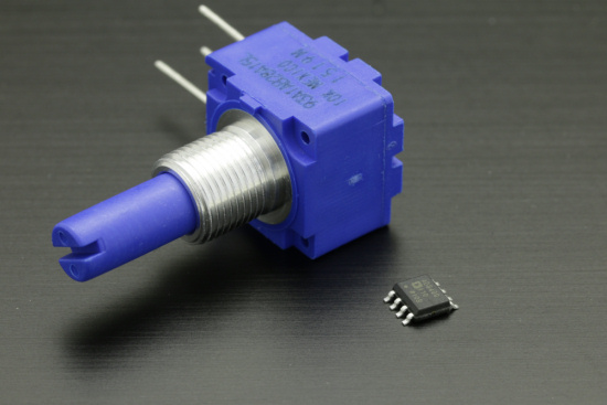
There are of course digital potentiometer chips, that we could easily interface to drive them from USB. But if you look closer at the specs, you will see that these chips have heavy limitations: they can hardly handle more than a few milliamps, and usually not more than 5V. This is why we do not think it would be worth doing a generic product based on these chips.

A digital potentiometer and a real one: they cannot be switched so easily
The DIY option
So it is unlikely that you get a Yoctopuce digital potentiometer any soon. However it is quite simple to build a USB-driven variable resistor using a few relays and well chosen resistors.
Principle
The principle is based on the fact that any positive integer can be represented as a sum of different powers of two. For instance:
42 = 2 + 8 + 32 = 21 + 23 + 25
Given that the total resistance of resistors connected in series is the sum of their individual resistance values, if we build a string of n resistors with values chosen as powers of 2, and we find a way to bypass the resistors which are not needed, then we can emulate any resistor between 0 and 2n-1. The simplest way to bypass a resistor is to connect a relay in parallel:

The principle behind our digital resistance
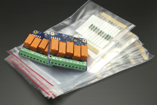
It is therefore very easy to create a digital variable resistor using very common resistors and a few relays. And we do have relays in stock...

A few relays and resistors, and you have it
The setup
We have have chosen to build a system that can emulate a resistor between 0 and 10230Ω by steps of 10Ω. So we needed resistors of 10, 20, 40, 80Ω... This looks fairly simple, but in real life, resistors with values which exactly match powers of two are not common. So the best is to combine values which are easy to find. We have chosen 1W resistors with 2% precision, and not used more than two resistors in series for each step, to keep the setup simple. We don't always get the exact desired value, but as long as the error is below the resistor tolerance, this does not really matter.
| desired value (Ω) | resistors | resulting value (Ω) |
|---|---|---|
| 10 | 10 | 10 |
| 20 | 10+10 | 20 |
| 40 | 39+1 | 40 |
| 80 | 68+12 | 80 |
| 160 | 150+10 | 160 |
| 320 | 270+47 | 317 |
| 640 | 560+82 | 642 |
| 1280 | 1.2K+82 | 1282 |
| 2560 | 2.2K+330+39 | 2569 |
| 5120 | 4.7K+390+39 | 5129 |
The resistors are bypassed using two Yocto-MaxiPowerRelays. Cabling is quite simple, as we can simply exit from one relay to enter into the next one. The order of values does not really matters, but the ideal is to interleave connection to the two relays to allow them to work in parallel when updating the bits in order.

The cabling scheme

The cabling, in real
Control software
The sotware part is easy, we only have to find the powers of two that make a given integer and turn on or off the corresponding relay. To make the programming easier, we gave to each relay logical name equal to the corresponding bit number: 0 for 10Ω 1 for 20Ω 2 for 40Ω etc. Here is the handling code, written in Python but which could have been in any other language:
from yocto_relay import *
bitcount = 10
factor = 10.0
maxvalue = factor*((1<<bitcount)-1)
# check parameters
if len(sys.argv)<2 :
scriptname = os.path.basename(sys.argv[0])
sys.exit("usage:" + scriptname + " value (0.."+str(maxvalue)+")")
value= int(sys.argv[1])
if value>maxvalue:
sys.exit("maxvalue is "+str(maxvalue))
# Setup the API to use local USB devices
errmsg=YRefParam()
if YAPI.RegisterHub("usb", errmsg)!= YAPI.SUCCESS:
sys.exit("init error"+errmsg.value)
value= int(value/factor)
# check for relays presence,s
relays = []
for i in range(0,bitcount):
relays.append(YRelay.FindRelay(str(1<<i)))
if not(relays[i].isOnline): sys.exit("cannot find any relay called "+str(1<<i))
# set relays
for i in range(0,bitcount):
if value & (1<<i):
relays[i].set_state(YRelay.STATE_A)
else:
relays[i].set_state(YRelay.STATE_B)
sys.exit("done")
And here is a small video of the live system:
Limitations et enhancements
It was quite easy to create a USB-driven variable resistor, but be aware that there is no magic and there are a few limitations nevertheless:
- It is a variable resistor with two terminals, which is not strictly equivalent to a potentiometer with three terminals and allows to create a voltage divider.
- Relay switching is not instantaneous, which means the resistor value may have an undesired transient value for a few milliseconds.
- Even if it is possible to configure the relays to keep a default value when powered on, they will all return to their max value when disconnected, corresponding to a value of ~10KΩ.
- As we use electromechanical relays, the total system consumption is significative: in our case, the worst case is a 0Ω value and uses approx 450mA on USB power supply.
It is possible to improve the concept using trimmers instead of each resistors, properly set once for all to values which are exactly powers of two, and in this way get an even higher precision, but at cost of a slightly reduced power tolerance.

The resistors can be replaced by trimmers
The code that we suggest is extremely simple, and it is possible to enhance it to reduce the transient values during value updates. It is also possible to enhance it to compensate for the imprecision of selected resistors.
Conclusion
It is unlikely that Yoctopuce sells an USB digital potentiometer any soon, but if you are not afraid of this bulky DIY solution, you can easily create a USB-driven variable resistor.


