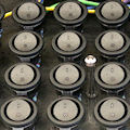
 If you have already tried to build a control panel interfaced by USB with many ON/OFF buttons, you know that it's not as simple as it may seem. Not only the multiplication of buttons makes the wiring process quickly complex, but if you are limited to 5 or 8 inputs per module, the number of interface modules that you must use increases rapidly. A way to improve these two issues consists in multiplexing several buttons on a single analog interface, and this is what we are going to show you today.
The multiplexing principle consists in adding distinct resistances for each button, so that the value read on the interface changes depending on the button which is activated. There are several possible connection typologies, depending on the criteria of the application. For this post, we are going to look at the most flexible case, that is the case which allows us to detect at any time any button combination, so that the state of a toggle switch doesn't prevent reading a temporary push button. The connection circuit must therefore ensure that you can differentiate the state of each button independently from the state of the other buttons with which it is multiplexed.
Here is the connection circuit that we recommend:

Interconnection diagram to multiplex switches
This circuit enables you to connect four switches per AnButton analog input. This makes it possible to read for instance 20 switches using a Yocto-Knob or even 24 switches using a Yocto-MaxiDisplay.
The values of the resistances were not selected randomly: they are current values that are easy to find and they were selected to minimise the risk of error by analog reading with the Yocto-Knob. We could have been bolder and have added a fifth switch with a 470Ω resistance, but depending on the tolerance of the resistances, the surrounding electromagnetic noise, and the length of the wires connecting the buttons, we would have risked reading errors. So we suggest that you stay with four buttons per input to maximize the reliability of the system.
On top of increasing the number of buttons available per input, this diagram has the advantage of considerable simplifying the wiring, compared to the trivial solution which consists in connecting each button on its own input. Here is what a 20 button control panel wiring looks like:


Building a control panel with 24 buttons multiplexed over six inputs
Let's now see how to read the values. The theoretical resistance of the circuit depending on the state of the buttons is thus the following:
| SW1 | SW2 | SW3 | SW4 | resistance | ratio |
|---|---|---|---|---|---|
| off | off | off | off | 17.7 KΩ | 100% |
| off | off | off | on | 16.7 KΩ | 94% |
| off | off | on | off | 15.7 KΩ | 89% |
| off | off | on | on | 14.7 KΩ | 83% |
| off | on | off | off | 13 KΩ | 73% |
| off | on | off | on | 12 KΩ | 68% |
| off | on | on | off | 11 KΩ | 62% |
| off | on | on | on | 10 KΩ | 56% |
| on | off | off | off | 7.7 KΩ | 44% |
| on | off | off | on | 6.7 KΩ | 38% |
| on | off | on | off | 5.7 KΩ | 32% |
| on | off | on | on | 4.7 KΩ | 27% |
| on | on | off | off | 3 KΩ | 17% |
| on | on | off | on | 2 KΩ | 11% |
| on | on | on | off | 1 KΩ | 6% |
| on | on | on | on | 0 KΩ | 0% |
So we do have a strong discrimination between possible values, with a minimum of 5% between each value. However, use resistances with a 1% accuracy to avoid the risk of errors, in particular for 10KΩ and 4.7KΩ resistances.
To decode the values, it's not useful to perform a bad approximation through a mathematical formula, because of irregular values. The simplest, the most reliable, and the fastest consists in identifying the state of each switch with four successive comparisons: one comparison to determine the state of SW1, then one to determine the state of SW2, and so on.
To make your life easier, we decided to add the implicit decoding of these states directly in the AnButton function available on analog inputs of Yoctopuce modules. Thus, if you update the firmware of your Yoctopuce modules equipped with AnButton functions, you now only need to configure in the module a digital input type, and the numerical value read on the AnButton function directly corresponds to the numerical encoding of the buttons considered as bits, therefore a number between 0 and 15 included. Not only it's easier to read, but it also allows the module to autonomously manage the anti-rebound filtering needed for an error free reading of mechanical switches. Don't hesitate to take advantage of it!


