![]() The widespread use of game controllers and augmented reality tools based on accelerometers and gyroscopes raises many ideas for applications. However, some of these applications are more a fantasy than a reality, as enthusiasm sometimes makes us forget some basic physical principles. So, here is a little reminder to help you avoid cruel deceptions...
The widespread use of game controllers and augmented reality tools based on accelerometers and gyroscopes raises many ideas for applications. However, some of these applications are more a fantasy than a reality, as enthusiasm sometimes makes us forget some basic physical principles. So, here is a little reminder to help you avoid cruel deceptions...
What is an inertial sensor?
An inertial sensor, such as the Yocto-3D-V2, includes a 3D accelerometer, a 3D gyroscope and a 3D compass.
- The 3D accelerometer allows you to measure the direction and the amplitude of the acceleration undergone by the sensor.
- The 3D gyroscope allows you to measure the angular speed of the sensor and the orientation of the rotation axis.
- The 3D compass allows you to measure the orientation of the external magnetic field compared to the module.
By combining these measures, we obtain an AHRS: A system able to estimate in real time its orientation in space. In a simplified way, it works like this:
- When idle, the inclination is measured with the accelerometer, trusting the direction of the gravitational acceleration measured by the sensor.
- Knowing the inclination, we compute the projection of the magnetic field on the horizontal plane and we deduce the orientation relative to the magnetic North.
- When moving, we integrate the angular speed measured by the gyroscope to update the orientation estimation.
Combining the sensors is actually performed with quite sophisticated mathematical tools, but this is the principle. By the way, these computations are performed directly by the Yocto-3D-V2 which provides a ready-for-use orientation estimation. And this does work rather well. This type of sensor allows you to stabilize a drone, or to detect brisk moves done on a game controller.
It is very tempting to extend this principle to obtain even more information, that is a full description of the movement in space described by the sensor. As we know the orientation of the sensor and the acceleration it undergoes, it is theoretically possible to estimate by integration its speed, and from there its position. It's the underlying principle of an inertial unit , used for example in aeronautics. So why not try it? As we are going to see, we unfortunately can't make an inertial unit based on a EUR 50 sensor.
Errors of integration and integration of errors
The first issue that we notice is that in an inertial unit, data are obtained by integration, that is by successive sums. However, measures can't be obtained really continuously. Therefore the sums necessarily introduce some small errors. Thus, even with a perfectly exact measure of the acceleration, we would end up with a speed estimation which is slowly drifting, depending on the accumulated errors. The position is obtained by integrating the speed, including its integration error. So the position error is quadratic relative to the initial approximations.
We can easily verify this on a digital simulation, by computing theoretical values returned by an ideal inertial sensor for an object which would go round a track a few times, stopping between each lap at the starting point. We integrate the acceleration and the speed, and we plot the trajectory deduced from the theoretical measures. Here are the simulation acceleration values, and the speed computed by integration:


And here is the obtained trajectory:

Digital integration simulation as an inertial unit would do it
The slight shift between each oval corresponds to the moment when the object is stationary between each lap. As the inertial unit cumulated tiny errors on speed, it doesn't know that the object is stationary and estimates that it is drifting.
This explains why even with an aeronautics inertial unit costing tens of thousands of dollars, based on accelerometers accurate to a few millionths of g and an angle estimate accurate to the hundredth of degree, an airliner flying horizontally during 5 hours without any other positioning methods would find itself several hundreds of kilometers away from the intended place....
Measure errors
If we transpose the same principle but using a small MEMS inertial sensor such as the Yocto-3D-V2, things get even more wrong: measure accuracy is far from an ideal measure, and the frequency of acceleration measures is lower.
To show the difference, we performed a small experiment. We put a Yocto-GPS and a Yocto-3D-V2 in a car. Then we made a short round trip going through two roundabouts to see if we could reconstruct the trajectory with our MEMS inertial sensor.
Here are the measures obtained with a Yocto-3D-V2 when you go through a roundabout at approximatively 30 Km/h:

Measures provided by a Yocto-3D-V2 for a car in a roundabout
The acceleration perpendicular to the movement, in light green, is that which causes the circular movement. Positive values correspond to the slight curve to the right when you enter the roundabout, negative values are the long rotation leftward, then again positive values for the slight curve to the right when exiting the roundabout. But we also see parasitic noise, some due to the sensor, others due to the vibrations in the car, in the order of +/-50 thousandths of g. This noise affects the measures, and is going to insert additional errors, which are also going to be amplified by the double integration. So much so that the integration of the raw data is completely useless.
Error reduction
So, how is it possible to make an orientation estimation by integrating a cheap gyroscopic sensor, but not a good speed estimation by integrating an accelerometer? The key to success is to have a method to constantly reduce the integration errors. In the Yocto-3D-V2, gyroscope integration errors are reduced by a combination with the orientation measure obtained by the accelerometer and the compass, which is less reactive but has the advantage of not drifting. It's therefore a slow correction which progressively and continuously voids the gyroscopic integration error.
In the particular case of a car trajectory discussed above, you can also perform a type of continuous error correction on the speed computation, by leveraging the fact that a car doesn't move laterally, but only in the direction of travel. Thus, we void the part of the cumulated error that is the perpendicular to orientation of the car. Here is the result:
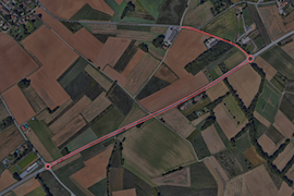
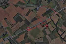
Journey measured by a Yocto-GPS, and journey computed on the basis of the MEMS inertial measures
The line on the left is measured by a Yocto-GPS, while the line of the right is determined with the inertial information provided by the Yocto-3D. Note how inertial information is largely insufficient for a reasonable position estimate, but that it is possible to reconstruct a semblance of trajectory. But if we had used a speed sensor rather than an acceleration integration, the result would have been much better. So next time you think of using an accelerometer to deduce a trajectory... think again and find another idea!

